Circuit diagrams – Carbolite VST Series User Manual
Page 12
HST, VST
12
MF13 – 3.40
7.0 C
IRCUIT
D
IAGRAMS
Safety Switches type A: A 2-pole Heater Switch is fitted directly in the element circuit in models
up to 16A rating. (Before mid-2000, up to 20A rating, 2 door switches were also fitted in this
position, in series with the Heater Switch.)
Safety Switch type B: A door switch is fitted into the contactor coil circuit. Above 16A a 1-pole
Heater Switch is fitted into the same circuit, in series.
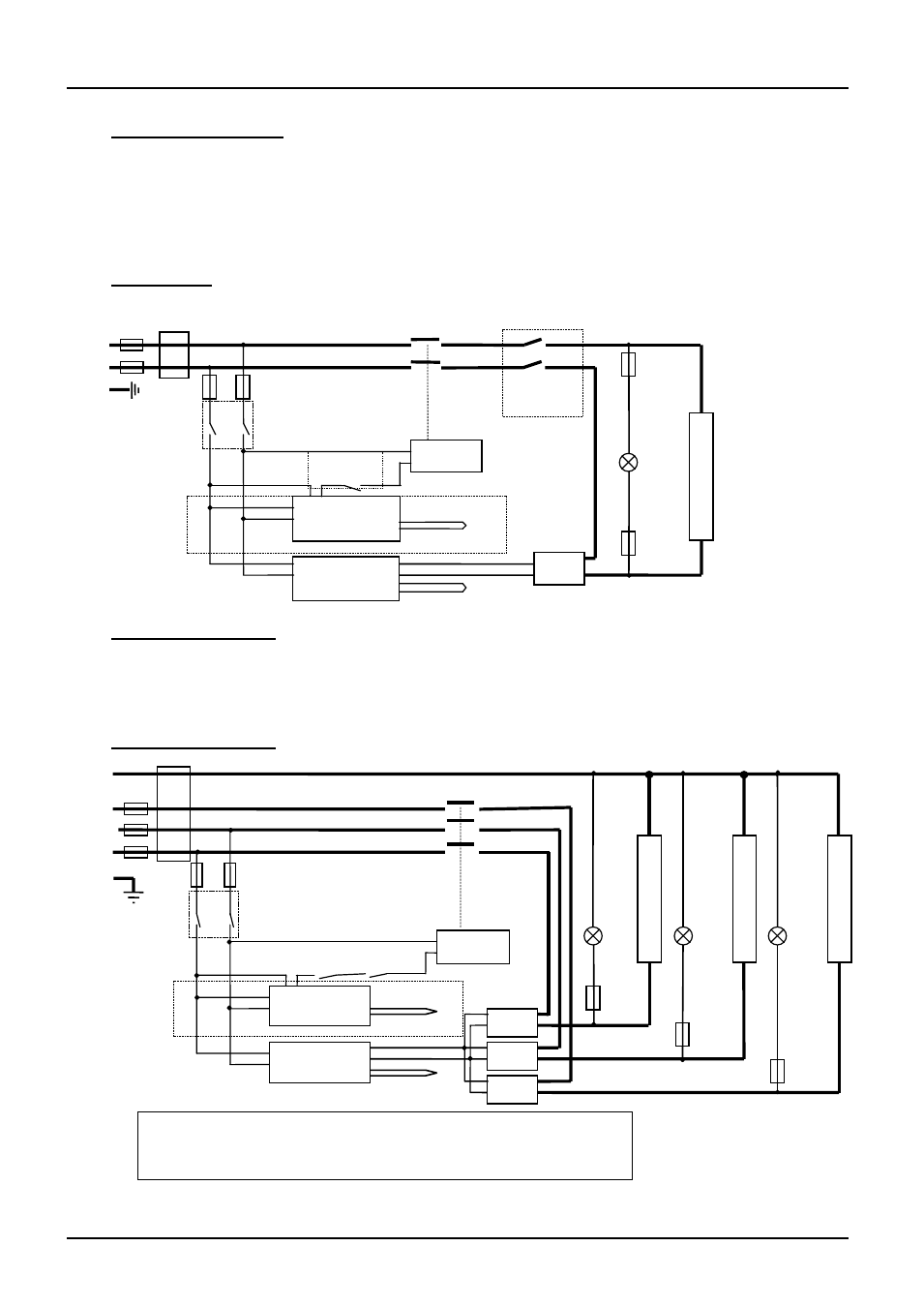
7.1 Single Phase
7.2 2-phase with neutral
As 3-phase, with phase L3 not present, and with two SSRs and element circuits.
In some models, before mid-2002, direct safety switches were fitted in the element circuit, rather
than the switch in the coil circuit as shown.
7.3 3-phase with neutral
Instrument Switch
coil
temperature
controller
thermocouple
overtemp.
controller
thermocouple
safety
switches B
SSR
e
l
e
m
e
n
t
(s)
heat
on
safety
switches A
F3
F1
F2
F3
N
L
PE
Filter
(if fitted)
contactor
or relay
if fitted
note on 3-phase: depending on filter(s) fitted, there may be 3
separate neutral wires from the elements to the neutral supply.
e
l
e
m
e
n
t
(s)
e
l
e
m
e
n
t
(s)
F1
N
L2
L3
F2
L1
PE
e
l
e
m
e
n
t
(s)
Instrument Switch
coil
temperature
controller
overtemp.
controller
safety switches
SSR
heat
on
F3
SSR
SSR
heat
on
F3
heat
on
F3
Filter (if fitted)
if fitted
thermocouple
thermocouple
contactor