Carbolite ELF Series User Manual
Page 13
ELF (B)
MF01 3.31
13
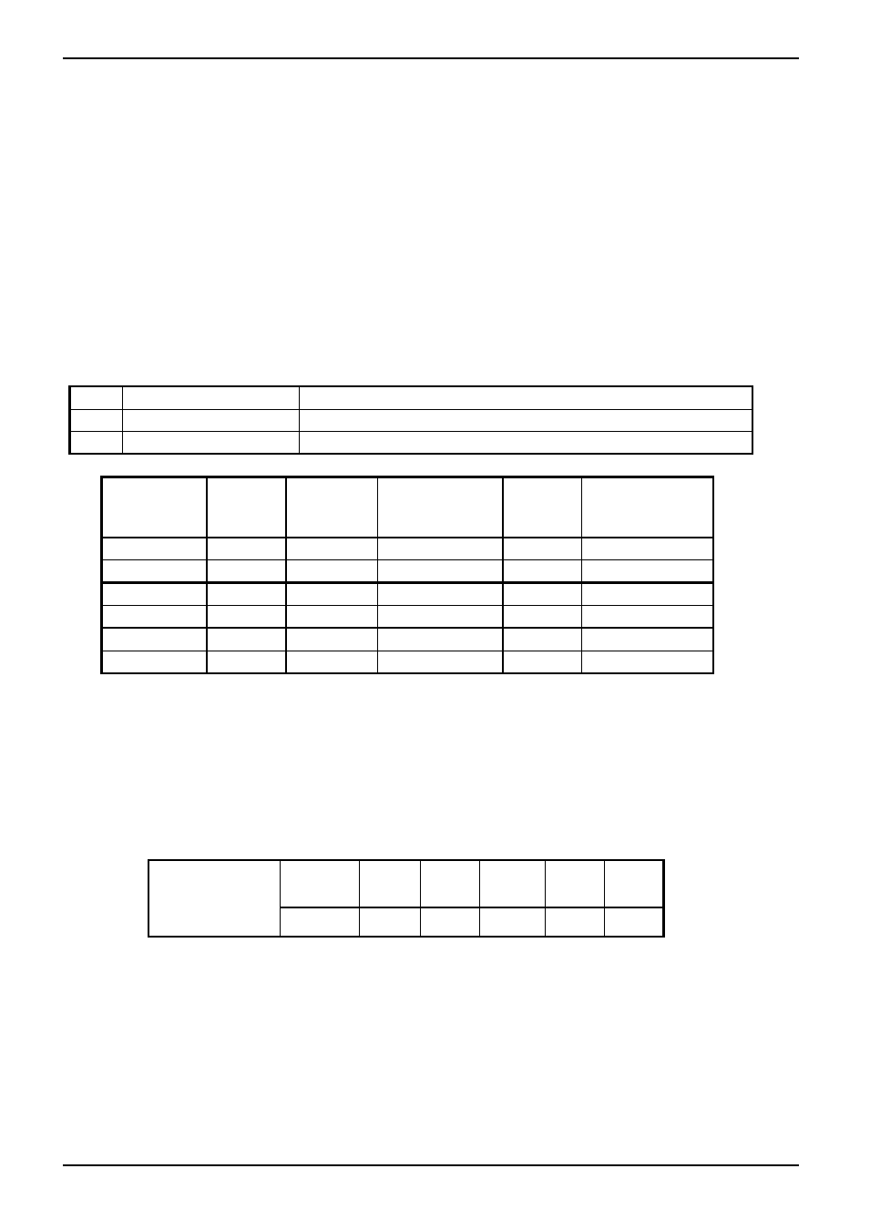
Fuses
8.2 Fuses are marked on the circuit diagram (above) with type codes, e.g. F1, F2. A list of the correct
fuses is tabled below.
If any fuse has failed, it is advisable for an electrician to check the internal circuits.
Replace any failed fuses with the correct type. For safety reasons do not fit larger capacity fuses
without first consulting Carbolite.
The fuses are near the cable entry point, and access is by removal of the back panel.
The fuses are mounted on an EMC filter circuit board. The smaller fuses F2 (when present) are for
the control circuit only.
F1-F2: Refer to the circuit diagram.
F1
Internal supply fuses
32mm x 6mm type F fitted on EMC filter circuit board(s)
F2
Auxiliary circuit fuses
20mm x 5mm type F fitted on EMC filter circuit board
Customer fuses
Use fast-blow fuses to minimum rating shown
Model
phases
Volts
Supply Fuse
Rating (Amps)
F1
Aux.
Fuse
F2
Customer Fuse
Rating
ELF 11/6B
1-phase
200-240V
10A (2 off)
2A*
10A
ELF 11/6B
1-phase
100-120V
10A (4 off)
2A
20A
ELF 11/14B 1-phase
200-240V
12.5A (2 off)
2A
12.5A
ELF 11/14B 1-phase
100-120V
12.5A (4 off)
2A
25A
ELF 11/23B 1-phase
200-240V
25A (2 off)
2A
25A
ELF 11/23B 1-phase
100-120V
50A (2 off)
2A
50A
* fuse not present unless overtemperature option is fitted
8.3 The furnace control system incorporates electronic power control, including a “power limit”
parameter that is used to reduce the effective voltage to 208V (or 104V); the values of the power
limit for different voltages are as follows:
ELF 11/6B
ELF 11/14B
ELF 11/23B
Voltage:
100
200
104
208
110
220
115
230
120
240
Power
100% 100%
89%
81%
75%