BASELINE Tire Changer User Manual
Page 23
Important: Always read and follow operating instructions.
• 19
6.
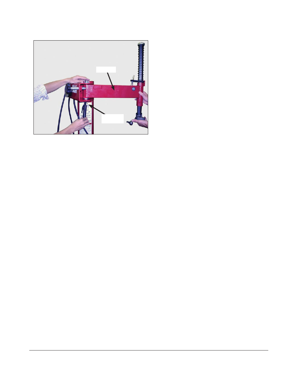
Remove swing arm bolt, washers and nut from
tower. Then, with the aid of a helper, position and attach
swing arm using bolt, washers and nut just removed
(figure 27). Torque to 55 - 75 ft. lbs.
Figure 27 - Install swing arm onto tower.
7.
Install air line and/or plug into power supply. Test
functionality (oil injector, pressure gauge function, etc.).
Air Source
The model 200 requires a 5 CFM air source at 120 PSI.
The operating pressure range is between 110 PSI and
175 PSI at the machine.
The unit is furnished with a 1/4” pipe thread male fit-
ting for easy connection. This connection is located on
the right side of the rear of the machine. A 1/4” ID hose
(or pipe) for connection to the machine is satisfactory.
Sufficient air pressure ensures good performance.
Electrical Source
Electrical models require power as follows:
15 amp, 115V electrical circuit
15 amp, 220V electrical circuit (Export)
Refer to the caution decal that is located by the unit’s
power cord.
Refer to the serial tag located on the lower part of
the machine for specific electrical requirements for
the unit. Have a licensed electrical technician perform
any necessary changes to the power source before
plugging in the unit. The electrical source must have a
solid connection (less than 1 ohm) between ground and
building ground.
Floor Mounting
The machine should be securely bolted to the floor
with suitable anchors using the hole at each corner of
the machine base.
Install Swing
Arm Bolt
Swing Arm