Configuring the activator, Connecting power – Axcess Activator Installation Guide User Manual
Page 9
Activator Installation Manual
© 202, AXCESS Inc.
750.001.006 R0003
9
Configuring the Activator
The Activator can be configured with its own user-defined location ID
via serial port (using a PC or terminal communications device) or
manually via jumpers. The unit installs easily and offers flexible
coverage for perimeter doors, interior zones, vehicle lanes and other
control points throughout the facility.
The following items are necessary for the successful configuration of
the Activator:
•
A computer with a terminal program and a free communications port
•
A standard one-to-one computer modem RS-232 cable with a DB9 male
connector (Receiver end) and a suitable connector for the PC/terminal
end
IMPORTANT! Do not
use a null-modem cable or null-modem adapter
.
Connecting Power
Activators come with a 24V DC, 1 Amp power transformer that plugs
into a standard 110V AC outlet. The transformer is pre-wired into the
terminal block at the factory. IF uninterruptible power is an issue, a
backup battery or UPS can be used.
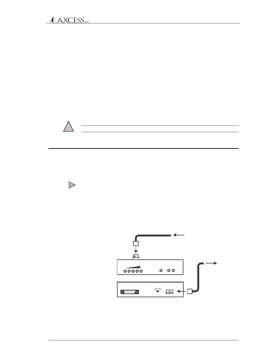
To connect power to the Activator
1: Connect the antenna to the Activator in order for the antenna
auto-tune feature to function when power is applied. Auto-tune
takes place each time power is cycled.
2: Plug the power terminal block into the back of the Activator
(Figure 3).
TX OUTPUT
PWR
TX RX
TM
TM
From
Transmit Antenna
BNC
Connector
Front Panel
GND +24VDC
POWER
RS-232
DATA
TX CNTL
-
+
Back Panel
Power
Terminal Block
To 24V DC
Source
Figure 3 Connecting power to the Activator
3: Plug the AC adapter into a 110-volt outlet.