Axcess Activator Installation Guide User Manual
Page 14
Activator Installation Manual
14
750.001.006 R04
© 2005, AXCESS Inc.
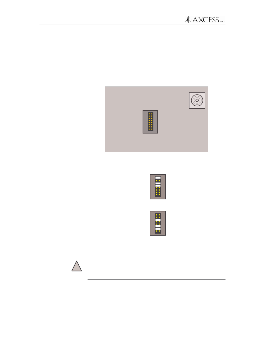
2: Carefully remove the lid from the Activator case and locate the
JP12-JP19 jumper block.
3: Using needle-nose pliers, place jumpers on headers JP12 through
JP19 (Figure 7) to represent the ID number in binary. A jumper
on a header represents a one and absence of a jumper is a zero.
JP12 is the least significant bit and JP19 is the most significant
bit.
Jumpers for setting the
Activator ID
JP12
JP19
Least Significant Bit
Most Significant Bit
Antenna BNC
Connector
Front of Activator
Figure 7 Activator ID Jumpers
JP12
JP19
Activator ID 13- 00001101
JP12
JP19
Activator ID 100 - 01100100
Figure 8 Examples of Activator IDs set with Jumpers
IMPORTANT!
Ensure that the Receiver is configured to accept the
new Activator ID so that it may process the Tag data properly.
Please see the
Network Receiver Installation Manual
for instructions
on programming the Receiver to respond to the new Activator ID.