Bbr ra ak ke e l la at th he es s – AMMCO 941053 Assembly User Manual
Page 2
2 • AMMCO
B
Br
ra
ak
ke
e L
La
at
th
he
es
s
W
Wh
he
en
n Y
Yo
ou
u R
Re
ec
ce
eiiv
ve
e
Y
Yo
ou
ur
r C
Ca
ab
biin
ne
et
t
Unpack the cabinet parts and check them against the
parts list on the last page of this manual. Make sure
you have all the parts listed – and the quantities listed.
Report any shortages immediately.
#
#9
94
41
10
05
55
5 B
Br
ra
ak
ke
e L
La
at
th
he
e
T
To
oo
ollb
bo
ox
x
Preparing the Bench for Use
1. Carefully lay the bench on its side.
2. Screw a leveling foot into the threaded hole
located at each corner of the bench (4 locations).
3. Once the bench is placed in its final location, level
the bench by raising or lowering the 4 leveling feet as
necessary.
4. Insert a plastic cap in all of the bench top holes
that will not be used for your lathe.
5. Attach lathe to bench.
6. Attach the funnel to the 2 holes in the top of the
left end panel. Use 2 truss head screws.
Figure – Attach Funnel
7. Place drawer liners in the four drawers.
#
#9
94
41
10
05
54
4 S
Siid
de
e S
St
to
or
ra
ag
ge
e
C
Ca
ab
biin
ne
et
t
Preparing the Cabinet for Use
1. Carefully lay the cabinet on its side.
2. Screw a leveling foot into the threaded hole
located at each corner of the cabinet (4 locations).
3. Once the cabinet is placed in its final location, level
it by raising or lowering the 4 leveling feet as necessary.
4. Place mat on top of cabinet.
5. Place drawer liners in the four drawers.
#
#9
94
41
10
05
53
3 T
To
oo
oll B
Bo
oa
ar
rd
d a
an
nd
d
L
Liig
gh
ht
t C
Ca
an
no
op
py
y
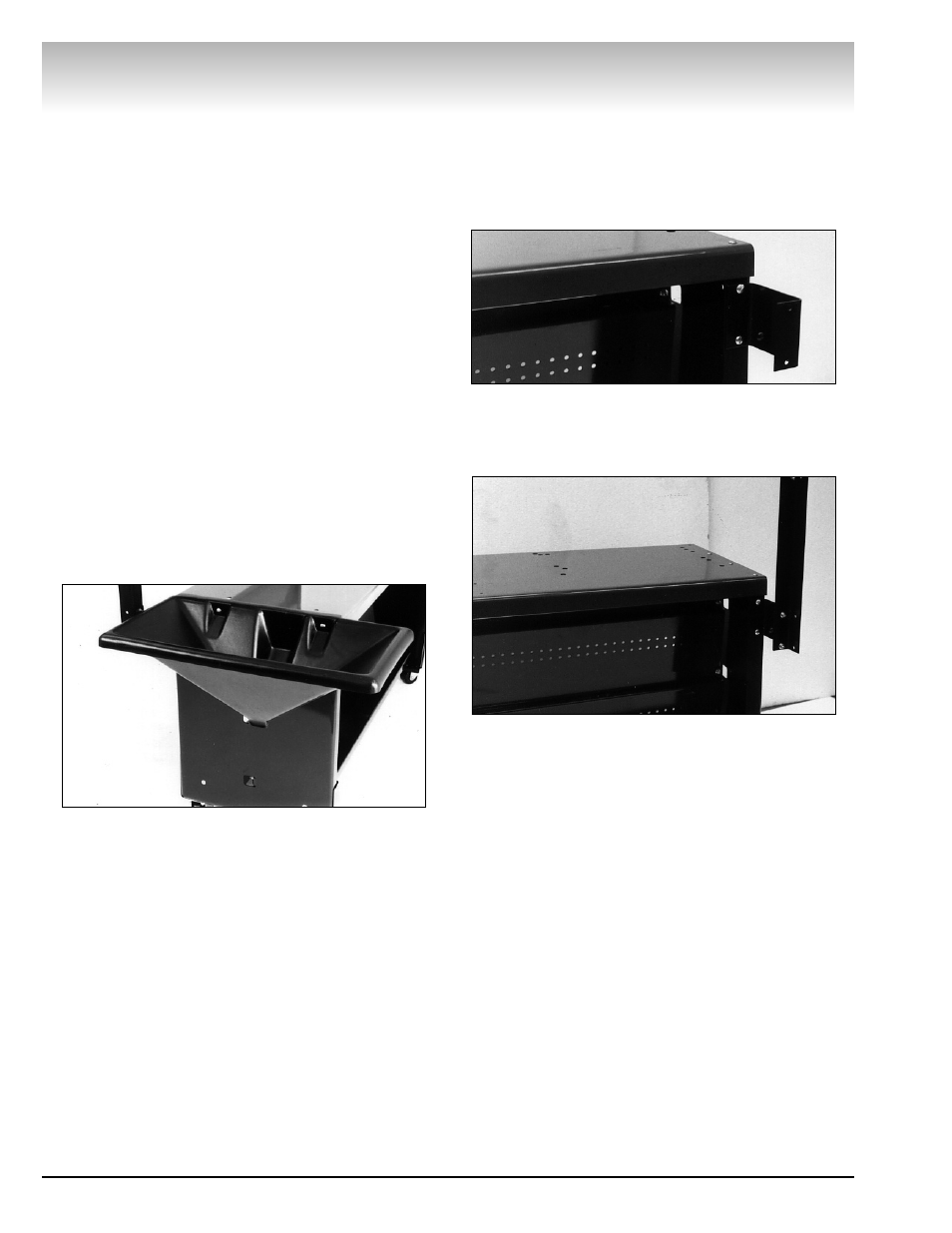
Attaching the Tool Board and Light Canopy
1. Use 3 truss head screws to attach each bracket to
the rear of cabinet. Wrench tighten.
Figure – Attach Brackets to Cabinet
2. Use 3 truss head screws and 3 flange nuts to
attach an upright to the bracket. Wrench tighten the
nuts. Repeat for the other bracket and upright.
Figure 2 – Attach Uprights to Brackets
3. Attach left-hand and right-hand canopy gussets to
the sides of the uprights using two truss head screws
and nuts for each. Wrench tighten.
4. Position the upper tool board behind the front
flanges of the uprights with the tool board flange on the
top and facing the rear. Secure the tool board to the
holes in the uprights with truss head screws and nuts.
Hand tighten the nuts only.
5. Fasten light fixture to light panel using screws and
nuts supplied with the light. Note that the light attaches
to the side of the light panel that has the front edge
formed down.
6. Lay light fixture panel assembly on top of gussets
with the formed edge pointing downwards at front of
cabinet. Secure panel to gussets with four truss head
screws and nuts.
7. Fasten the sign to the front of the light canopy
with two truss head screws and nuts.
8. Wrench tighten all hardware.