Usb soundcard routing, Allen & heath 34 xone:db4 user guide – Allen&Heath XONE DB4 User Manual
Page 34
Allen & Heath
34
XONE:DB4 User Guide
USB SOUNDCARD ROUTING
R
I
A
A
R
I
A
A
PH/LN
ADC
ANA
D
IG
C
H
A
N
N
E
L
P
F
L
CUE
CHANNEL SOURCES
CHANNEL SOURCES
Each of the USB audio sends can source from various points within
the XONE:DB4 Input Channels. From the diagram, the three
options are Analogue In, Digital In and Channel PFL.
ANALOGUE IN - The analogue sources are arranged as follows:
CHANNELS 1 AND 4 - LINE INPUT ONLY
CHANNELS 2 AND 3 - SWITCHABLE LINE /PHONO
DIGITAL IN - The source connected to the channel’s digital input.
CHANNEL PFL - The channel PFL is the point in the signal path
where monitoring is done using the channel CUE button. The
Channel PFL is after the EQ, Loop and FX sections, so any
manipulation of these areas will be audible.
P
H
O
N
E
S
M
IX
R
E
C
O
R
D
B
O
O
T
H
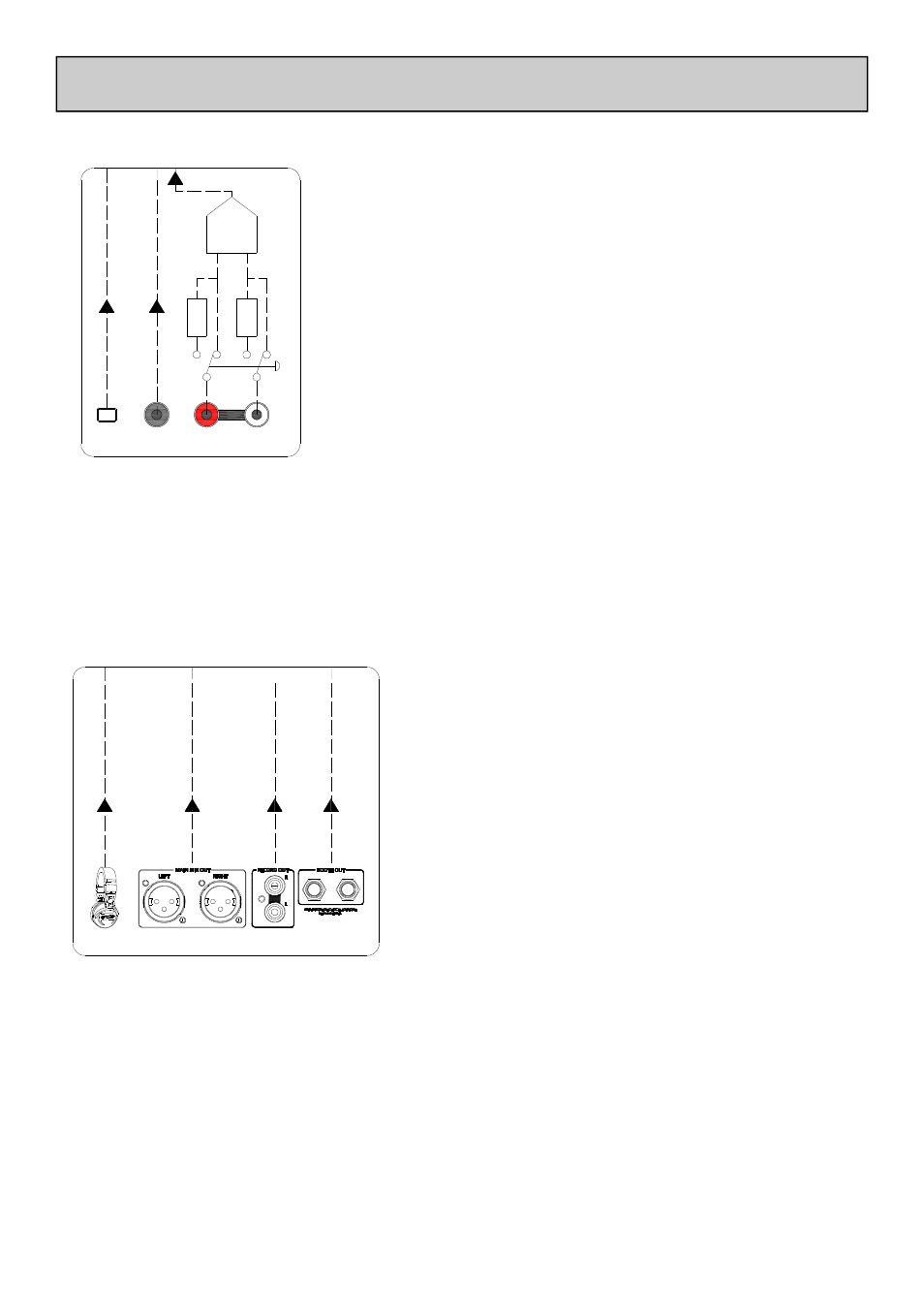
MIXER SOURCES
MIXER SOURCES
MIX OUTPUT - Routes the Mix Output to the chosen send. For more information on Mix Output
source options, please refer to Page 28.
PHONES OUTPUT - Routes the Phones Output to the chosen send. For more information on
Phones Output source options, please refer to Page 27.
MAPPING A SOUNDCARD INPUT SEND
For details on selecting Soundcard Input Send sources please see “USB Routing” on Page 27.
The USB audio sends can also source from any of the
mixers outputs.
From the diagram, the four options are the Booth Output,
Record Output, Mix Output and Headphone (CUE bus)
Output.
BOOTH OUTPUT - Routes the Booth Output to the
chosen send. For more information on Booth Output
source options, please refer to Page 28.
RECORD OUTPUT - Routes the Record Output to the
chosen send. For more information on Record Output
source options, please refer to Page 28.
MICROPHONE INPUT
The microphone input can be recorded into software by setting its selector switch to ‘CH1’ (see Page
9) and setting one of the input sends to CHANNEL 1 PFL.