Removing the power supply pcb (dl1000) – Allen&Heath DP 1000 SERVICE MANUAL User Manual
Page 8
8
icon
series
Removing the Power Supply PCB (DL1000)
Before beginning any service work, remove all power to the unit and disconnect any signal cables where
necessary. Adopt static electricity working procedures when carrying out service work. Ensure
adequate lighting and use the correct tools. Access to the Power Supply circuit board can only be
achieved once the console has been opened (see ‘Opening up the DL1000 console’).
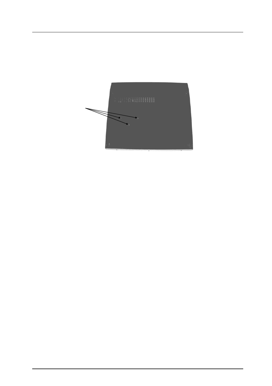
1)
Turn the console base over to reveal underside. Referring to fig.4 remove the 3 heat-sink
screws.
2)
Remove the 2 XLR screws from the rear of the base and drill out the 2 Mains Inlet IEC pop
rivets (see fig.5)
3)
The Power Supply circuit board assembly can now be removed from the console.
When all service work is complete, remove all debris such as solder, component legs and wire clippings
from inside the unit and check your work carefully before re-assembly. To refit the Power Supply circuit
board assembly, follow the above procedure in reverse order. Make sure all Earth wires are aligned and
plugged on. Test for correct operation.
fig.4
3 heat-sink screws