Removing the cpu pcb – Allen&Heath DP 1000 SERVICE MANUAL User Manual
Page 14
14
icon
series
Removing the CPU PCB
Before beginning any service work, remove all power to the unit and disconnect any signal cables where
necessary. Adopt static electricity working procedures when carrying out service work. Ensure
adequate lighting and use the correct tools. Access to the CPU circuit board can only be achieved once
the console has been opened (see ‘Opening up the DL/DP1000 console’)
1)
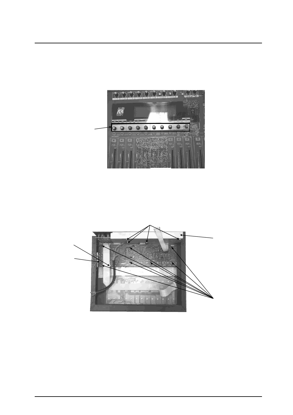
Remove the 10 rotary encoder knob caps (see fig.13)
2)
Remove the 4 nuts from the Audio Shield (see fig.14), retaining the crinkle washer. Remove
Audio shield.
3)
Remove the 7 screws from the CPU circuit board (see fig.14)
4)
Remove the 2 connecting IDC Harnesses from the CPU circuit board and cut the connecting
cable tie (see fig.14)
5)
Detach all other cables and harnesses from the CPU circuit board (note: the CPU to Fader IDC
is siliconed on at the CPU circuit board, the silicone bond will have to be broken to release the
CPU to Fader IDC)
6)
The CPU circuit board assembly can now be removed from the console.
When all service work is complete, remove all debris such as solder, component legs and wire clippings
from inside the unit and check your work carefully before re-assembly. To refit the CPU circuit board
assembly, follow the above procedure in reverse order. Make sure all harnesses are aligned and
plugged on. Test for correct operation.
fig.13
Rotary Knobs
Audio Shield
Audio Shield Nuts
fig.14
CPU PCB
CPU to chassis screws
Cable Tie