Removing the toroid transformer (dp1000), Toroid transformer mains wiring, Icon – Allen&Heath DP 1000 SERVICE MANUAL User Manual
Page 12: Series
12
icon
series
Brown
16.5V
Blue
16.5V
White
0V
Red
0V
Red
9V
Orange
0V
Black
42.7V
Yellow
42.7V
Green or
Green/Yellow
Transformer
Earth screen
Blue
0V
Live (see table
for different
territories)
Voltage
Primary Winding Colour
Brown
240V
Red
220V
120V
Black
White
110V
Grey
100V
Amplifier
PCB
Toroid
Transformer
Mains
PCB
Green Earth wire
Green
Earth
fig.11
Removing the Toroid Transformer (DP1000)
Before beginning any service work, remove all power to the unit and disconnect any signal cables where
necessary. Adopt static electricity working procedures when carrying out service work. Ensure
adequate lighting and use the correct tools. Access to the Toroid Transformer can only be achieved
once the Amplifier circuit board has been removed (see ‘Removing the Amplifier Circuit Board
Assembly’).
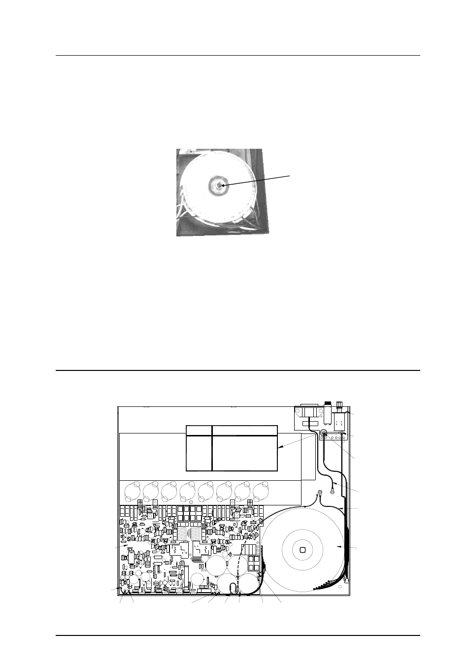
1) Referring to fig.10 remove the Toroid Transformer bolt.
2) Referring to fig.11, de-solder all transformer wires from the Amplifier circuit board and remove the
green or green & yellow Transformer earth wire from the right earth post (see fig.11). Pull off the
two transformer wires connected to the Mains circuit board.
3) Remove the Toroid Transformer from the console.
To refit the Toroid Transformer, follow the above procedure in reverse order. Make sure all Transformer
wires are re-soldered correctly. Test for correct operation.
Toroid Transformer Mains Wiring
The diagram below shows the Transformer Mains wiring for different territories, when re-fitting the
transformer be sure to re-connect the wires as shown.
fig.10
Toroid Transformer Bolt