5 rear panel – AirLive VoIP-400 Series User Manual
Page 11
ITG User’s Guide
SYSTEM
Green Blinking The system is running. (Heartbeat LED)
LAN
y
ACT
y
100M
y
LNK
y
COL
Green
Green
Green
Green
On
On
Off
On
On
Data is presented on LAN.
The gateway is connected to LAN at 100Mb/s.
The gateway is connected to LAN at 10Mb/s.
The gateway is connected to LAN.
Data collision is occurring on the network connection.
LINE
Channels
1-4
Reset Button
Green Off
On
Blinking
The line is idle.
The line is being used.
The line is ringing.
There is a push button located behind a small hole next to the SYSTEM LED. This button
allows you to reset the ITG or force the ITG to enter firmware upgrade mode.
To reset the gateway, push a small, stiff object into the hole until the SYSTEM LED stops
blinking, then release the button.
Powering on the gateway while pressing down the button for 5 seconds forces the ITG to
enter download mode
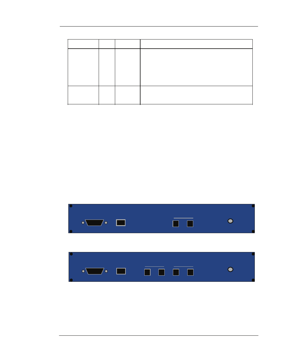
1.5 Rear Panel
The rear panel of the ITG has two FXS ports for 2 ports ITG and four ports with two FXO
and two FXS ports for 4 ports ITG. Depending on the type of the telephony interface. The
telephony interface ports may be connected to telephony devices, such as PBX, KTS, and
telephone sets of central office. In addition to the telephony interface ports, there is an power
adapter connection hole on the rear panel.
Console LAN
FXS
12VDC
Figure 1-1 2 ports ITG Rear Panel
Console LAN
FXO FXS
Figure 1-2 4 ports ITG Rear Panel
12VDC
LAN / Console Ports
The ITG is equipped with an Ethernet interface with 10/100 Mbps
auto-negotiation capability. The Ethernet interface port is located on the rear panel. In addition
to the Ethernet
Overview
11