2n® smartgate umts quickstart, Basic functions, 2n® smartgate umts installation and connection – 2N Analogue UMTS gateway 2N SmartGate UMTS - Quick Start, 1713 v1.00 User Manual
Page 2: Led indicators
2N® SmartGate UMTS QuickStart
Basic Functions
•
Primarily, the device is intended for
voice
transmission
between
the
GSM/UMTS network and connected line
telephone sets.
•
Detailed routing tables include a lot of
settings and help cut your call costs
dramatically.
•
Using a PC, you can get access to the
high-speed Internet (GPRS,
EDGE,
WCDMA, HSDPA) and send/receive
SMS.
•
You can send SMS to one pre-defined
number via a SMS input.
•
The battery backed-up 2N® SmartGate
UMTS version allows you to maintain your
traffic even in the event of power outage.
•
The 2N® SmartGate UMTS firmware can
be upgrade f
Read the CD-ROM User Manual carefully to get familiar with all the 2N®
SmartGate UMTS functions.
2N® SmartGate UMTS supports the 3G WCDMA/HSDPA, GSM GPRS/EDGE
technologies for data connection. The connection speed and quality
depend on the UMTS/GSM provider, accessible services, signal coverage
and network conditions. The parameters included in the User Manual
(Technical Parameters) are the maximum values; for detailed information
about accessible services contact your mobile provider.
2N® SmartGate UMTS Installation and Connection
•
Proper Location
- Install 2N® SmartGate UMTS with respect
to a good UMTS/GSM signal intensity.
- Place 2N® SmartGate UMTS out of range
of sensitive devices and human bodies for
electromagnetic interference reasons.
- 2N® SmartGate UMTS is designed for
indoor use. Do not place it near heat
sources. It may not be exposed to direct
solar radiation, rain, flowing water and
moisture, aggressive gas, solvents etc.
•
Needed Accessories
INCLUDED IN 2N® SMARTGATE UMTS PACKAGE
• 1 2N® SmartGate UMTS
• 1 power adapter (12V/1A DC)
• 1 antenna including supply cable (SMA)
• 1 telephone cable
• 1 USB A/B cable
• 1 SMS input connector
• 2 screws with dowels
• 1 User Manual and SW CD
NOT INCLUDED IN 2N® SMARTGATE UMTS PACKAGE
• SIM card
• Provider’s information on Internet
connection (APN, etc.)
•
External Antenna Connection
Screw the enclosed antenna into the
SMA antenna connector. Tighten the
antenna connector gently with your
hand, never use a wrench!
•
SIM Card Installation
Insert the SIM card into the SIM card
slot on the 2N® SmartGate UMTS
bottom (connector) side as shown in
the figure and make sure that the
security latch has clicked into position.
Select the required provider and SIM
card services, such as call forwarding,
call barring, preferred networks, SMS
centre, etc., using your mobile phone
before inserting your SIM card in 2N®
SmartGate UMTS.
•
Connection to FXO Interface
A device with the FXS interface can be
connected to the FXO interface (e.g. a
PBX internal line).
•
Connection to FXS Interface
A device with the FXO interface can be
connected to the FXS interface (a
standard
analogue
telephone,
answering machine, PBX external line).
2N® SmartGate UMTS is equipped with
the FSK-based CLIP function on the
FXS interface and so you are advised to
connect a CLIP displaying terminal
device.
•
Mains
Supply
Connection
and
Switch On
2N® SmartGate UMTS is 12V DC
voltage powered. Connect the attached
power adapter (12V/1A DC) to the
power
supply
connector.
After
connection, switch on 2N® SmartGate
UMTS with the power switch on the
right-hand bottom side.
•
Battery Supply Connection and
Switch On
Insert four AA-type batteries into a
compartment on the back side of the
backed-up 2N® SmartGate UMTS
gateway. Refer to the compartment
label for proper battery placement and
polarity.
Do not connect the antenna as long as the device is in operation to avoid
GSM/UMTS module damage.
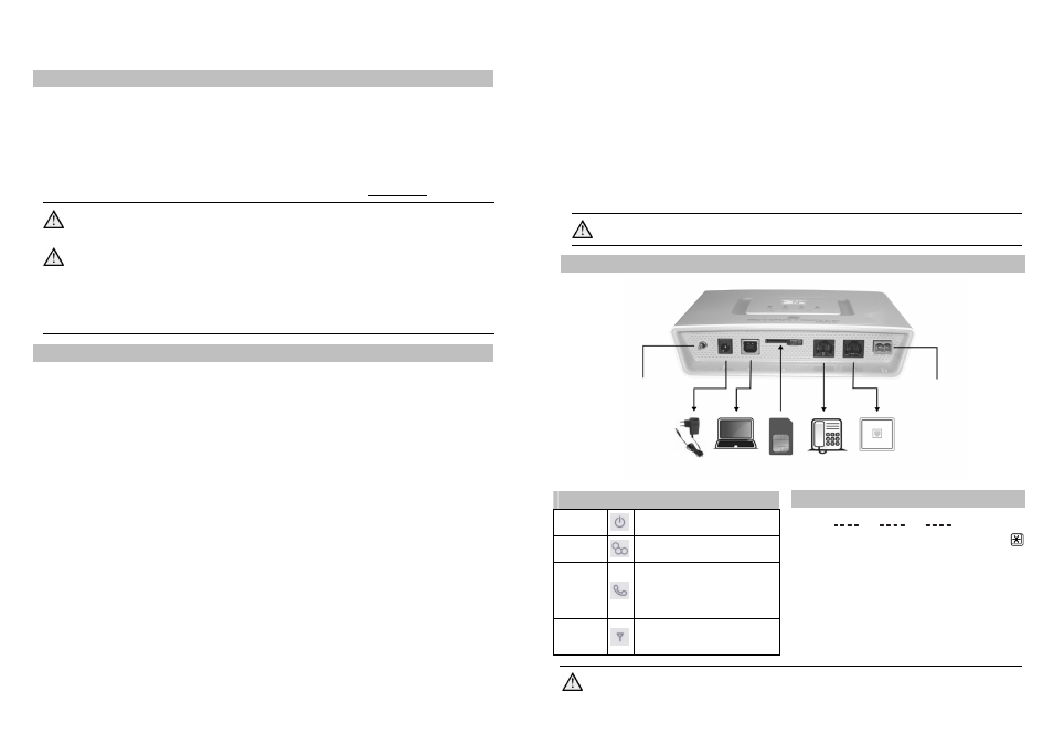
Example of 2N® SmartGate UMTS Connection
PIN Secured SIM Card
1. Hook off the telephone and hear the PIN
tone:
2. Enter the PIN using DTMF and press
for confirmation. Hang up the line to
cancel a wrong PIN.
3. If you hear the busy tone after a while (a
few seconds), the PIN has been entered
correctly. This PIN will be entered
automatically upon every power up.
4. If you hear the PIN tone again after a
while, the PIN has not been entered
correctly. Re-enter the PIN.
By entering three wrong PINs you block the SIM card. Enter the PUK code
into your mobile phone to unblock the SIM card.
LED Indicators
Power
supply
Blue light – mains supply
Yellow light – battery supply
GSM
UMTS
Blue flashing –logged out
Blue light – logged in
Telephone
line
No light – Standby
Orange LED – FXS interface active
Green LED – FXO interface active
Flashing – line off-hook or ringing
Light – call in progress
Alternating LED – call FXS - FXO
Signal/
Battery
indicator
1 is shining – minimum
4 are shining – maximum
Signal – during ready state
Battery –upon off-hook on FXS line
Power adapter
IN: 110V-240V AC
OUT: 12V/1A DC
SMS input
PBX internal line
(FXS interface)
Analogue
telephone
(FXO interface)
SIM
Power switch
ON/OFF
(backed-up version)
PC (USB)