5 replacing drive belt (670cc model), 6 replacing the flex hose, 7 replacing wear liners – Echo DL10570 Owners Manual v.1 User Manual
Page 22: Warning
Debris Loader Owner’s Manual
18
SERVICE AND MAINTENANCE
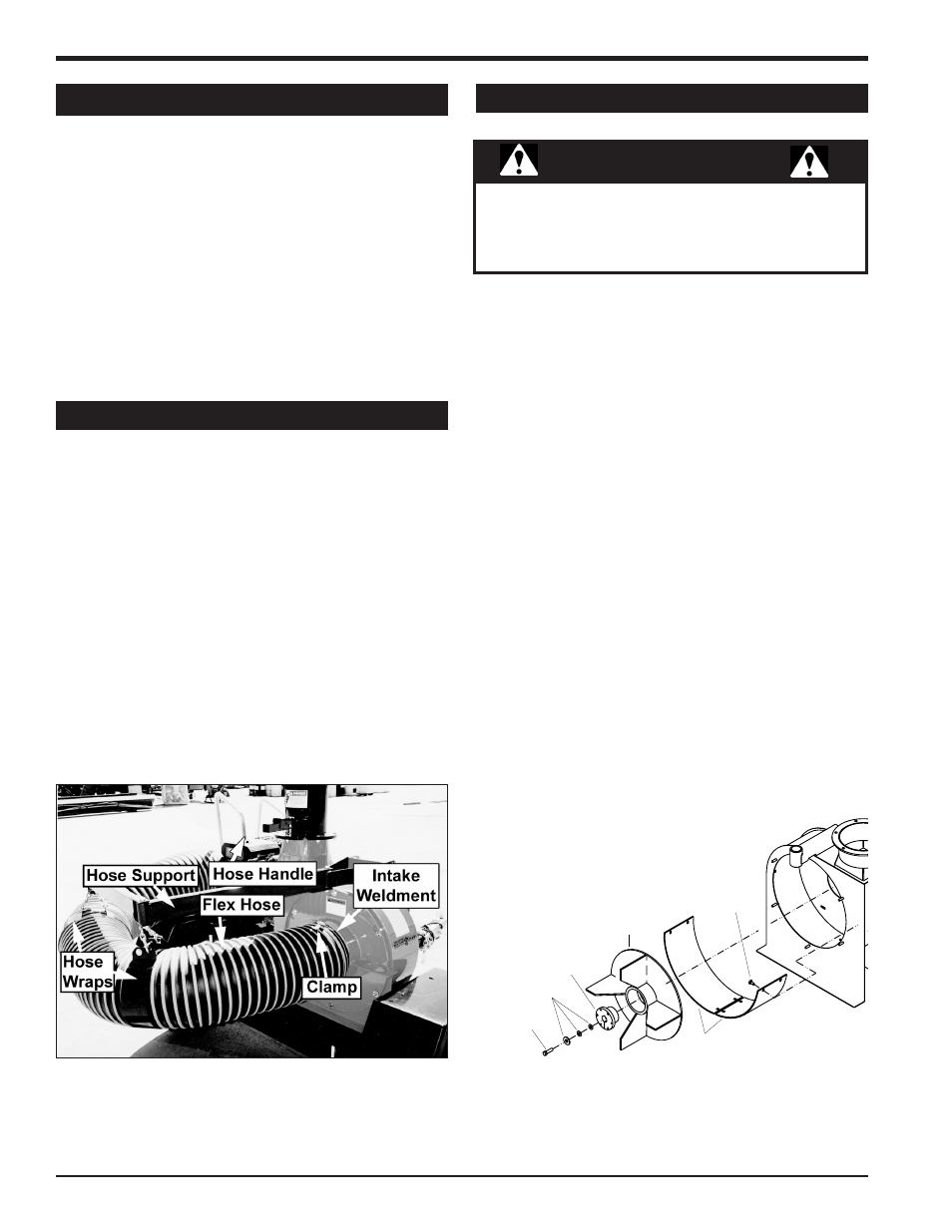
Check the condition of the flex hose frequently. Replace
if it is split or damaged.
1. Shut off engine and allow rotor to completely stop.
2. Remove spark plug wire.
3. Remove the clamp attaching the flex hose to the hose
intake weldment. Remove the hose from the intake
weldment (Figure 19).
4. Remove two bolts from the hose wraps to separate
the flex hose from the hose support.
5. Remove the remaining clamp securing the flex hose
to the hose handle. Remove the hose from the hose
handle.
6. Replace flex hose by performing steps 1-5 in reverse
order.
5.6 REPLACING THE FLEX HOSE
Figure 19, Flex hose (670cc Honda model shown)
5.5 REPLACING DRIVE BELT (670cc MODEL)
12. Tighten the four carriage bolts securing the engine
plate to the trailer.
13. Tighten the jam nut to ensure the proper deflection is
maintained.
14. Reinstall belt guide. Adjust so there is 1/8" clearance
between the belt and the belt guide.
15. Move the engagement lever to the start position.
16. Reinstall the belt shield.
17. Reconnect spark plug wire.
5.7 REPLACING WEAR LINERS
The fan housing wear liners are replaceable on 725cc,
570cc & 390cc engine models. To replace the wear
liners:
1. Remove the fan intake weldment from the fan hous-
ing.
2. Remove the 7/16" x 1-1/2" bolt and washers from the
end of the engine crank shaft (Figure 20).
3. Remove the bushing and rotor from the engine crank
shaft.
4. From the outside of the debris loader housing, remove
eight 5/16" nylock nuts that hold the two wear liners.
5. Remove the old wear liners and insert the new lin-
ers.
6. Install the new wear liners with eight 5/16" x 3/4" car-
riage bolts and nylock nuts. Feed the carriage bolts
from inside the debris loader housing. Torque hardware
to 17 ft-lbs.
7. Reinstall the bushing and rotor on the engine crank
shaft.
8. Reinstall the 7/16" x 1-1/2" bolt and washers to the
engine crank shaft. Torque to 50 ft-lbs.
9. Make sure approximately 1/4" clearance exists be-
tween the fan housing and the rotor plate.
WEAR
LINERS
ROTOR
BUSHING
7/16” x
1-1/2” BOLT
WASHERS
5/16” x 3/4”
CARRIAGE
BOLT
5/16”
NYLOCK NUT
Figure 20, Flex hose (670cc Honda model shown)
Before inspecting or servicing any part of this machine,
shut off power source, disconnect spark plug wire from
spark plug and make sure all moving parts have come
to a complete stop.
WARNING