3 replacing chipping blades – Echo 77412 Owners Manual v.1 User Manual
Page 19
Page 17
4.5" BearCat Chipper Operator's Manual
SERVICE AND MAINTENANCE
The chipping blades should clear the chipping anvil located
directly under the chipper chute by 1/16 inch. To adjust the
blade clearance, proceed as follows:
1.
Removing the chipper chute is NOT required for setting
the chipping blade clearance, although, removing the
chipper chute can provide better access for measuring
the chipping blade clearance.
2.
Rotate the disk until a chipping blade is even with the
chipping anvil.
3.
Measure the amount of clearance between the chip-
ping blade and chipper anvil from inside of the chipper
housing. The gap should be 1/16 inch (Figure 5.3).
4.
Adjust the anvil by loosening the 5/16" x 5/8" bolts
holding the anvil to the disk cover and sliding the anvil
inward or outward until the desired measurement is
achieved.
5.
Tighten the bolts and torque to 75 Ft-lbs.
6.
IMPORTANT: Repeat for the remaining chipping blades.
7.
Reinstall the chipper chute.
If the chipping anvil edge is damaged or worn unevenly,
remove the three bolts and washers holding the anvil to the
disk cover and use one of the other three edges. Adjust for
correct measurement.
5.3 REPLACING CHIPPING BLADES
If the chipper blade does not extend beyond the disk chip-
ping slot, follow the steps below to replace the chipping
blade:
1.
Remove the chipper deflector or discharge tube.
2.
Lock rotor assembly (Section 5.1).
3.
Remove the two 1/2" x 1-3/4" flat head screws holding
the blade to the disk.
4.
Remove the old blade, install the new blade and torque
to 75 Ft-lb. Repeat this procedure for each blade.
5.4 SETTING CHIPPING BLADE
CLEARANCE
5.5 ADJUSTING THE DRIVE BELT
Check the condition of the drive belt annually or after every
25 hours of operation, whichever comes first. Replace a
cracked, frayed, worn or stretched drive belt. Only replace
drive belt with original banded type belt. Do not use single
type belts. To adjust the drive belt, proceed as follows:
1.
Move the chipper engagement lever to the start posi-
tion.
2.
Shut engine off.
3.
Disconnect battery cables.
4.
Remove the belt shield by removing the seven 5/16" x
3/4" bolts securing the belt shield to the shield weldment.
5.
Loosen the 5/16" bolt attaching the belt guide to the
engine.
6.
To increase tension on the belt, do the following:
6a. Loosen the four carriage bolts attaching the
engine plate to the trailer.
6b. Locate the two 5/16" x 2" bolts and 5/16" flange
nuts located on the side of the chipper between
the trailer and the engine plate.
6c. Loosen both 5/16" flange nuts.
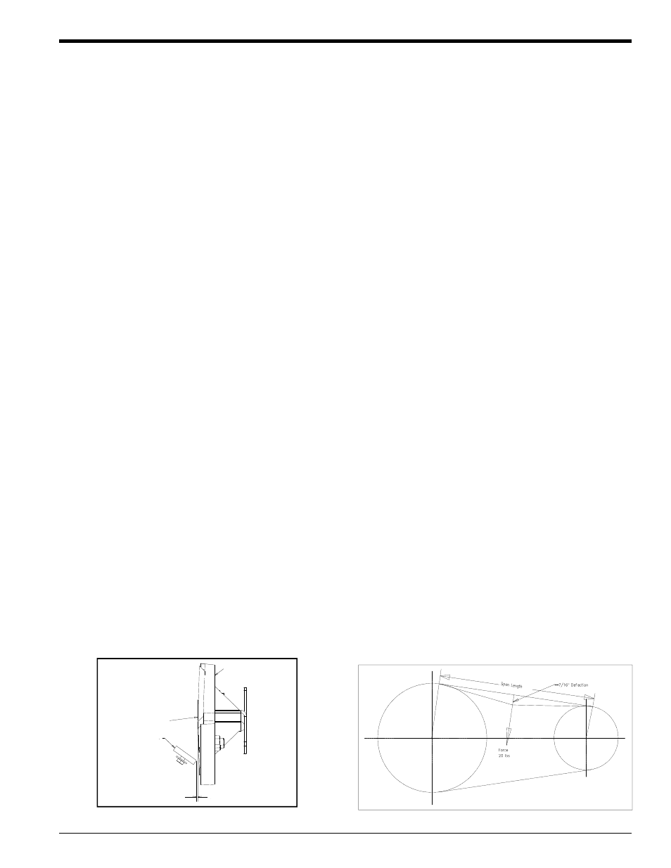
6d. Tighten both 5/16" bolts equally to move the
engine away from the chipper housing until the
belt deflection is 7/16" when a 20 lb. load is
placed against the belt (Figure 5.4).
6e. Tighten the four carriage bolts securing the en-
gine plate to the trailer.
6f. Once the proper deflection is achieved, tighten
both 5/16" flange nuts to ensure the proper de-
flection is maintained.
7.
If the bolts and nuts between the engine plate and the
trailer cannot be adjusted any further and the tension
needs further adjustment, tighten the eyebolt until the
appropriate deflection is achieved.
8.
Replace the belt if no adjustment is left (Section 5.6).
9.
Replace belt shield.
Figure 5.4 - Belt Tension
Figure 5.3 - Chipper Blade and Anvil Clearance
Chipper Disk
Chipper
Blade
Anvil
1/16"