Echo 77412 Owners Manual v.1 User Manual
Page 11
Page 9
4.5" BearCat Chipper Operator's Manual
ASSEMBLY
HITCH ASSEMBLY
1.
Attach the hitch channel to the bottom of the trailer:
1a.Standard Configuration (Figure 2.6 & 2.7): At-
tach the hitch channel on the end closest to the
engine using two 3/8" carriage bolts, 3/8" washers
and 3/8" nuts.
1b. Optional Configuration (Figure 2.8): Attach the
hitch channel on the end furthest away from the
engine using two 3/8" carriage bolts, 3/8" washers
and 3/8" nuts.
2.
Attach the coupler and the coupler handle onto the hitch
pole using two 1/2" x 3-1/4" bolts, 1/2" washers and
1/2" nuts.
3.
Attach the safety chains, one on each side of the hitch
pole, using one 3/8" x 3-1/2" bolt, four washers (one on
each side of both safety chains) and one nut.
5.
Attach the nylon lanyard to the hitch pole using one
1/4" x 3/4" bolt and 1/4" locknut. Attach a hitch pin to
the lanyard.
4.
Attach the jack stand to the hitch pole using one 3/8" x
3" bolt, 3/8" washer and 3/8" nut. Use a hitch pin to
secure the jack in the raised position.
6.
Insert the hitch pole into the hitch channel and attach
using one bolt, washer and nut. Secure with a hitch
pin.
LIGHTS
When assembling models 77413 and 77413S into the Op-
tional Configuration, the lights on the trailer need to be moved.
Follow the steps below to move the lights:
1.
Remove the bolts securing the RH light bracket and the
LH light bracket to the trailer.
2.
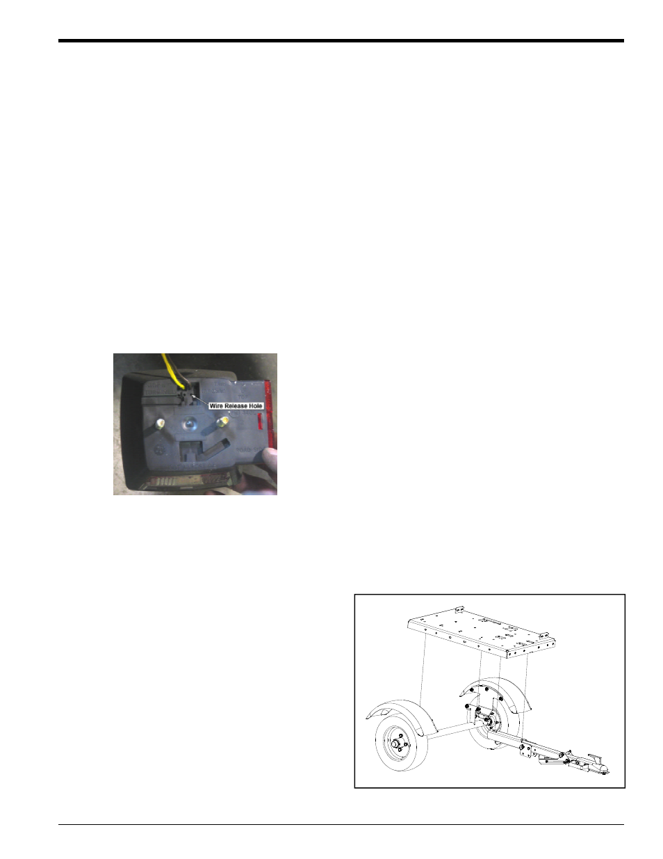
Disconnect the trailer light wiring harness from the lights
by pushing a small screwdriver or punch into the wire
release hole (Figure 2.5).
3.
Cross the lights and secure them to the other end of the
trailer. The RH light will become the LH light and the LH
light will become the RH light.
4.
Connect the wiring harness.
5.
Test the blinkers and brakes to ensure the lights are
properly connected.
2.2.2 MODELS 77413, 77413S
AXLE AND WHEEL ASSEMBLY
1.
Assemble the grease seal, bearings, hub assembly,
cotter pin and wheel cap onto one side of the axle.
Repeat for the other side.
2.
Slide a wheel onto the axle and secure with four wheel
bolts. Torque the wheel bolts to 75 Ft-lb. Repeat for the
other wheel.
3.
Position the trailer onto the axle using a hoist or jack:
3a. Standard Configuration (Figure 2.6 & 2.7): The
axle and wheels should be positioned at the end
furthest away from the engine. Locate the holes
on the sides of the trailer furthest from the engine.
Align these holes to the top holes on the axle sup-
port brackets located on the axle. Secure with two
3/8" x 1" bolts, 3/8" washers and 3/8" nuts on each
side.
3b. Optional Configuration (Figure 2.8): The axle
and wheels should be positioned at the end clos-
est to the engine. Locate the holes on the sides of
the trailer closest to the engine. Align these holes
to the top holes on the axle support brackets lo-
cated on the axle. Secure with two 3/8" x 1" bolts,
3/8" washers and 3/8" nuts on each side.
4.
Attach the fenders to the bottom holes on the axle sup-
port brackets using two bolts, washers and nuts.
Figure 2.5 - Trailer Lights
Figure 2.6 - Standard Trailer/Hitch Assembly
(Models 77413, 77413S)