6 attach license plate light, 7 attach discharge chute, 8 fill the tank – Echo CH611DH Owners Manual v.5 User Manual
Page 13: English
9
6 INCH CHIPPER
ENGLISH
ASSEMBLY
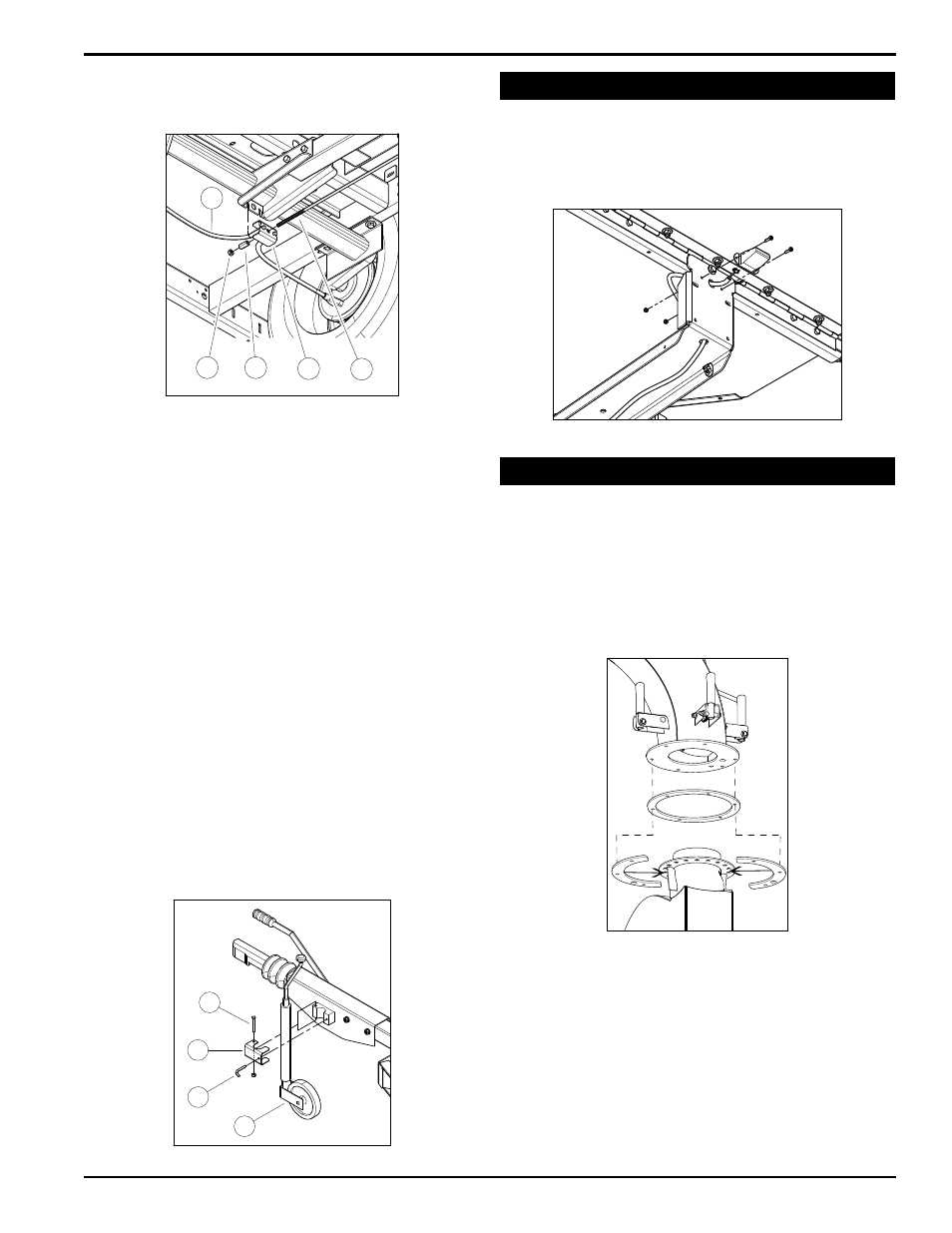
Figure 2.7, Brake rod connection at axle
Figure 2.8, Pivot jack mounting
Figure 2.10, Mount the discharge chute on the chipper by using
the discharge ring and two discharge retainers
5. Bolt the chute to the chipper with six (6) 3/8” x 1-1/2”
bolts and nuts from the owner's kit. The bolts should
go through the chute, discharge ring, and discharge
retainer.
6. Tighten to proper torque.
7. lubricate the chute by applying grease to the grease
zerk at the base of the chute. Rotate the chute and
apply grease until the chute rotates freely.
8. use the snap pin from the owner's kit to lock the chute
in position.
2.7 aTTach DischarGe chuTe
1. Place the discharge ring around the base of the
mounting flange on the chipper frame (Figure 2.10).
2. use a hoist to position the discharge chute directly
above the mounting flange.
3. Position the discharge ring around the mounting
flange.
4. Position the two discharge retainers (half circles)
below the mounting flange.
Figure 2.9, CE Compliant license plate light
2.6 aTTach license plaTe liGhT
(CE Compliant models only)
1. Attach the license plate light to the chute support, which
is located under the feed chute, with two #10-24 nuts
and two #10-24 x 1/2 screws.
2. Plug the wire harness into the license plate light.
8. Insert the other end of the brake control rod in to the
center hole of the balance bar bracket (12) at axle
location.
12
9
13
14
15
16
17
18
19
9. Next, insert the ends of the brake cable lines (13) in to
the outside holes of the balance bar bracket.
10. Secure the balance bar bracket to the brake rod by
threading the M10 x 35mm spherical nut (14) on to the
brake rod making sure that the convex end of the nut
is toward the bracket. This nut will be the adjustment
point for setting brake tension.
11. Adjust the length of the brake rod so there is no play
without any pre-load.
12. Once proper brake adjustments are set, thread the
final M10 hex nut (15) on to the brake rod end and
tighten securely against the spherical nut to prevent it
from loosening,
13. Place pivot jack (16) into position on the coupler
assembly mounting bracket.
14. Align jack clamp bracket (17) over the jack and secure
to the coupler mounting bracket by vertically inserting
an M8 x 140mm bolt (18) through the holes. Add
nylock nut and tighten securely while still allowing
clamp to pivot.
15. Secure jack at desired height by inserting threaded
handle (19) through clamp bracket, into threaded hole
of mounting bracket and tighten.