Assembly, 1 attach trailer wheels, 2 attach pintle hitch – Echo CH911DH Owners Manual v.2 User Manual
Page 10: 3 install rear stabilizer, 4 attach chute and support, Warning, Important
9 INCH CHIPPER
6
Section
ASSEmbLY
2
2.1 ATTACH TRAILER WHEELS
Remove the chipper from its shipping crate. Place the
1.
unit on a level surface before attempting to assemble
it.
Raise the trailer several inches from the ground with a
2.
hoist or jack. Support the chipper securely.
lift one wheel to a hub and align the wheel lug holes
3.
with the hub lug bolts. Thread the lug nuts onto the
bolts and tighten them to 75 ft-lbs. Follow a star pattern
when tightening the lug bolts. Repeat this step for the
remaining wheel.
NoTE
Axle and hitch assemblies for some models are
supplied by the distributor and may vary from the
illustrations shown below.
2.2 ATTACH PINTLE HITCH
Insert the adjustable hitch into the hitch opening in the
1.
chipper trailer.
Attach the pintle hitch ring to the adjustable hitch with
2.
two 5/8" x 4-1/2" bolts, washers, and centerlock nuts.
Torque the bolts to 160 ft-lbs.
Connect the safety chains to the adjustable hitch
3.
weldment as shown in Figure 2.1. Use a 3/8" x 2-1/2"
bolt, two washers, and a nylock nut to attach the safety
chains.
Push the top link pin through the holes in the hitch and
4.
trailer. Secure the top link pin with a lynch pin.
Adjust the ring on the pintle hitch to make the chipper
trailer as level as possible when connected to the towing
vehicle.
SAFETY
CHAIN
3/8” x 2-1/2”
BOLT
3/8”
WASHER
5/8” x 4-1/2”
BOLT
PINTLE
RING
5/8” CENTERLOCK
NUTS
5/8”
WASHERS
3/8”
WASHER
3/8”
NYLOCK
NUT
LYNCH
PIN
TOP LINK
PIN
Figure 2.1, Trailer hitch assembly
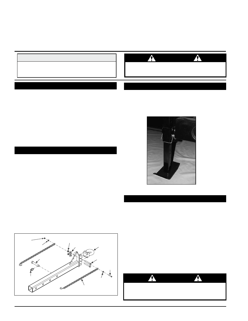
The rear stabilizer (Figure 2.2) is installed by sliding the
stabilizer into the trailer support guide on the rear of the
chipper frame. The stabilizer is secured and adjusted with
the provided snap pin.
2.3 INSTALL REAR STAbILIzER
Figure 2.2, Rear stabilizer
2.4 ATTACH CHuTE AND SuPPoRT
Use a support or hoist to hold the chipper chute in
1.
place on the hydraulic feed (Figure 2.3).
Attach the chute support to the rear end of the trailer
2.
using one 3/8" x 2" bolt, washer and locknut. Torque
to 35 ft-lbs. Refer to Figure 2.3 for proper positioning
of the weldment.
Attach the chipper chute to the hydraulic feed using
3.
eight 3/8" x 1-1/2" carriage bolts and nylock nuts. use
three bolts on each side and two on the bottom. To in-
sert the top bolts, rotate the feed roller until the cut-out
in the side of the drum matches the bolt holes.
WARNING
Do not operate this unit without the chipper chute
correctly installed. Rotating cutting blades can cause
serious personal injury.
ImPoRTANT
If any bolts or nuts are dropped in the machine, be
sure to remove them before starting the machine.