Spindle-brake sub-assembly, Spindle-brake sub-assembly -46 – JLG 800S Service Manual User Manual
Page 92
SECTION 3 - CHASSIS & TURNTABLE
3-46
– JLG Lift –
3121139
Spindle-Brake Sub-Assembly
NOTE: This procedure applies only to units with integral
input brake (2).
NOTE: For this procedure, use the Brake Assembly Drawing
(Figure 3-36.), which will show the proper balloon
numbers for the individual brake components. In the
following instructions, if the number has a “-”
between two numbers, it refers to the Brake Assem-
bly Drawing only and NOT the Torque Hub Assembly
Drawing.
NOTE: The Pressure Plug (12) requires a special tool for
installation. It is not recommended to remove this
plug unless it is leaking. The plug is called a Koenig
Expander. The installation tool is not supplied by
Fairfield manufacturing, but can be supplied by the
manufacturer of the Koenig Expander, Sherex Indus-
tries, or one of their distributors.
1. Install Pressure Plug (12) into Spindle (1A) using fol-
lowing procedure:
• Clean hole in spindle using appropriate Loctite spray
• Dip collar of plug in Loctite 290 or 680 (keep
unplugged portion of hole free of Loctite)
• Using appropriate tool, install plug flush with surface of
spindle
SAFETY GLASSES MUST BE WORN DURING THE NEXT STEP.
2. Place Spindle (1A) such that the splined end is fac-
ing down. Using appropriate tool (See back of man-
ual), install Retaining Ring (2-1) into the spindle
groove within the splines.
3. Place Washer (2-10) on top of Retaining Ring (2-1).
4. Place Stator (2-9) on top of Washer (2-10).
5. Place Rotor (2-12) on top of Stator (2-9).
6. Repeat steps 3 & 4 until there are a total of 8 Stators
(2-9) and 7 Rotors (2-12) installed.
7. Place Piston (2-8) such that the smaller O.D. end is
facing upward.
8. Grease the large Backup Ring (2-3) and install in the
large-diameter groove at the bottom of the Piston (2-
8).
9. Grease the large O-Ring (2-2) and install in the
large-diameter groove at the bottom of the Piston (2-
8), on top of the large Backup Ring (2-3).
10. Grease the small O-Ring (2-5) and install in the
small-diameter groove near the top of the Piston (2-
8). Make sure the O-Ring is seated on the bottom of
the groove.
11. Grease the small Backup Ring (2-4) and install in the
small-diameter groove near the top of the Piston (2-
8), on top of the small O-Ring (2-5).
NOTE: If piston comes pre-assembled with shipping bolts
(2-11), skip to Step 15.
12. Insert Piston (2-8) into Spindle (1A) until it contacts
the Stator (2-9).
13. Insert the appropriate number of Springs (2-13) into
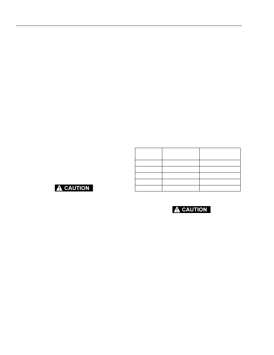
Piston (2-8) counterbore. Use the brake spring chart
below and a bill of materials for your particular
model number to determine the number of springs.
14. Place Pressure Plate (2-7) on top of Springs (2-13).
SAFETY GLASSES MUST BE WORN DURING THE NEXT TWO
STEPS.
15. Using snap ring pliers, install Retaining Ring (2-6)
into groove in Spindle (1A) and on top of Pressure
Plate (2-7). Make sure that Retaining Ring (2-6) is
seated properly in the groove.
16. Remove Shipping Bolts (2-11) in brake pressure
plate to release springs in brake. Before removing
bolts, use the Coupling (9) (See Assembly Drawing
at back of manual) to center and align the Brake
Rotors (2-12) with the Spindle (1A).
BRAKE
CODE
BRAKE P/N
NUMBER
OF SPRINGS
A
902337
12
B
902341
10
C
902342
8
D
902343
6
E
902345
9