Boom disassembly, Boom disassembly -2, Location of components - boom powertrack -2 – JLG 800S Service Manual User Manual
Page 218
SECTION 4 - BOOM & PLATFORM
4-2
– JLG Lift –
3121139
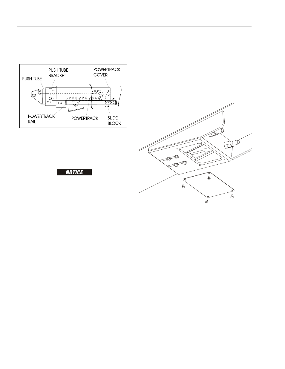
h. With powertrack support and using all applica-
ble safety precautions, remove bolts #3 and #4
securing rail to the base boom section. Remove
powertrack from boom section.
4. Remove boom assembly from machine as follows:
a. Using suitable lifting equipment, adequately
support boom assembly weight along entire
length.
HYDRAULIC LINES AND PORTS SHOULD BE CAPPED IMMEDI-
ATELY AFTER DISCONNECTING LINES TO AVOID ENTRY OF CON-
TAMINANTS INTO SYSTEM.
b. Tag and disconnect hydraulic lines from tele-
scope cylinder. Use a suitable container to retain
any residual hydraulic fluid. Cap hydraulic lines
and ports.
c. Remove hardware securing the lift cylinder rod
end to the base boom section.
d. Using a suitable brass drift and hammer, remove
the lift cylinder pin from the base boom.
e. Remove hardware securing the master cylinder
rod end to the base boom section.
f. Using a suitable brass drift and hammer, remove
the master cylinder pin from the base boom.
g. Remove hardware securing the boom pivot pin
to the turntable upright.
h. Using a suitable brass drift and hammer, remove
the pivot pin from the turntable upright.
i. Using all applicable safety precautions, carefully
lift boom assembly clear of turntable and lower
to ground or suitably supported work surface.
Boom Disassembly
NOTE: The following procedure assumes the boom is
removed from the machine.
1. Extend the boom approximately 2 feet (0.6 m). This
will enable access to the bolts that secure the cable
mount block to the boom fly section.
2. Remove hardware securing the telescope cylinder.
3. Remove hardware securing the cover plate on the
bottom front of the base boom section.
NOTE: Do not allow wire rope to rotate. This may damage
the wire rope.
4. Clamp both threaded ends of wire rope to prevent
rotation. Note: Do not clamp on threads. Remove
jam nuts and nuts which secure the wire rope
adjustments to the bottom front of the base boom
section.
Figure 4-3. Location of Components - Boom Powertrack