Main disassembly, Main disassembly -36, Main disassembly drawing 1 -36 – JLG 800S Service Manual User Manual
Page 82
SECTION 3 - CHASSIS & TURNTABLE
3-36
– JLG Lift –
3121139
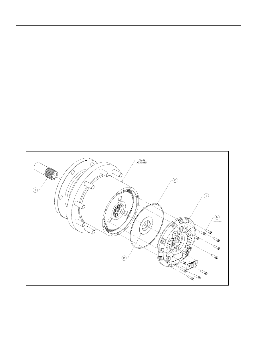
Main Disassembly
1. Perform Roll Check, Leak Check and Brake Check if
applicable prior to disassembling the unit.
2. Drain oil from unit. Note the condition and volume of
the oil.
3. Remove Input Coupling (9) from Spindle (1A) end of
unit.
4. Remove Cover Bolts (14) and remove Cover (6).
5. Remove O-ring (19) and Thrust Spacer (10) from the
Cover (6).
6. Remove Input Sun Gear (17) from Input Carrier Sub-
Assembly (3A).
7. Remove Input Carrier Sub-Assembly (3A) from
Housing (1E).
8. Remove Output Sun Gear (8) from Output Carrier
Sub-Assembly (4A).
9. Remove Input Shaft (7) from Output Carrier Sub-
Assembly (4A).
10. Remove Output Carrier Sub-Assembly (4A) from
Housing (1E).
Figure 3-28. Main Disassembly Drawing 1
6. Cover
9. Input Coupling
10. Thrust Spacer
14. Cover Bolts
19. O-ring