12 rotary coupling - s/n 81836 to present, Rotary coupling - s/n 81836 to present -62, Coupling port information table - 2ws -62 – JLG 600A_AJ Service Manual User Manual
Page 112: Coupling port information table - 4ws -62
SECTION 3 - CHASSIS & TURNTABLE
3-62
– JLG Lift –
3121201
3.12 ROTARY COUPLING - S/N 81836 TO
PRESENT
Use the following procedure to install the seal kit.
1. If not already removed, remove the axle oscillation
valve from the cylinder barrel. The spool of the valve
protrudes into the barrel and will damage the spool
and seals if left in place.
2. Remove snap ring (12) from end.
3. Remove thrust ring (13) from the same end.
4. Remove center body (10) from housing (11).
5. Cut off old seals (14,15,17,18).
6. Assemble lip seals (14) in direction shown in Figure
3-49., Rotary Coupling - Sheet 2 of 2.
7. Reassemble O-ring (18).
8. Heat cap seals (17) in hydraulic oil for 5 minutes at
300° F (149° C).
9. Assemble cap seals over O-rings
10. Reinsert center body into housing (lube with hydrau-
lic oil).
11. Replace thrust ring and snap ring.
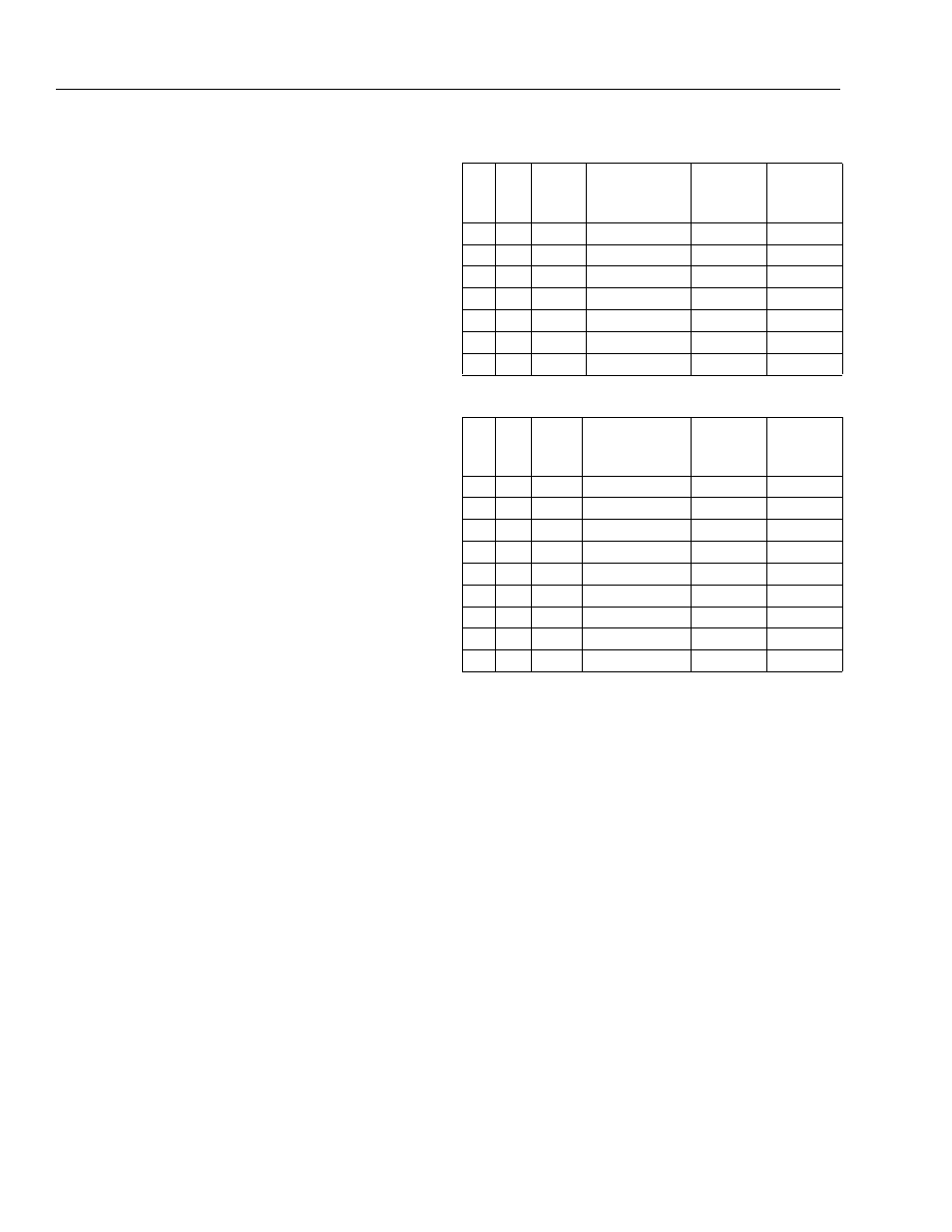
Table 3-9. Coupling Port Information Table - 2WS
Port
No.
Outlet
Port
Size
Description
Operating
Pressure
PSI (Bar)
Proof
Pressure
PSI (Bar)
1
1
-8
Brake
450 (31)
675 (47)
2
2
-6
2 Speed
4500 (310) 6750 (465)
3
1
-6
Steer
2500 (172) 3750 (259)
4
1
-6
Steer
2500 (172) 3750 (259)
5
2
-6, -16
Drive Reverse
4500 (310) 6750 (465)
6
1
-16
Drive Forward
4500 (310) 6750 (465)
7
3
-8, -6
Case Drain
250 (17)
375 (26)
Table 3-10. Coupling Port Information Table - 4WS
Port
No.
Outlet
Port
Size
Description
Operating
Pressure
PSI (Bar)
Proof
Pressure
PSI (Bar)
1
1
-8
Brake
450 (31)
675 (47)
2
2
-6
2 Speed
4500 (310) 6750 (465)
3
1
-6
Steer
2500 (172) 3750 (259)
4
1
-6
Steer
2500 (172) 3750 (259)
5
2
-6, -16
Drive Reverse
4500 (310) 6750 (465)
6
1
-16
Drive Forward
4500 (310) 6750 (465)
7
3
-8, -6
Case Drain
250 (17)
375 (26)
8
1
-6
Steer
2500 (172) 3750 (259)
9
1
-6
Steer
2500 (172) 3750 (259)