11 final drive and travel motor, Removal, Final drive and travel motor -25 – JLG 600SC_660SJC Service Manual User Manual
Page 87: Removal -25, Final drive required tools - removal -25, 11 final drive and travel motor removal
SECTION 4 - CAT CHASSIS (PRIOR TO S/N 0300128000)
3121157
– JLG Lift –
4-25
4.
Install bolts (1). Tighten bolts (1) to a torque of 270
± 40 Nm (200 ± 30 lb ft).
5.
Connect the track assembly. Refer to Section 4.5,
Track.
6.
Remove the cribbing from the front roller.
4.11 FINAL DRIVE AND TRAVEL MOTOR
Removal
CARE MUST BE TAKEN TO ENSURE THAT FLUIDS ARE CON-
TAINED DURING PERFORMANCE OF INSPECTION, MAINTE-
NANCE, TESTING, ADJUSTING AND REPAIR OF THE PRODUCT.
BE PREPARED TO COLLECT THE FLUID WITH SUITABLE CON-
TAINERS BEFORE OPENING ANY COMPARTMENT OR DISASSEM-
BLING ANY COMPONENT CONTAINING FLUIDS.
DISPOSE OF ALL FLUIDS ACCORDING TO LOCAL REGULATIONS
AND MANDATES.
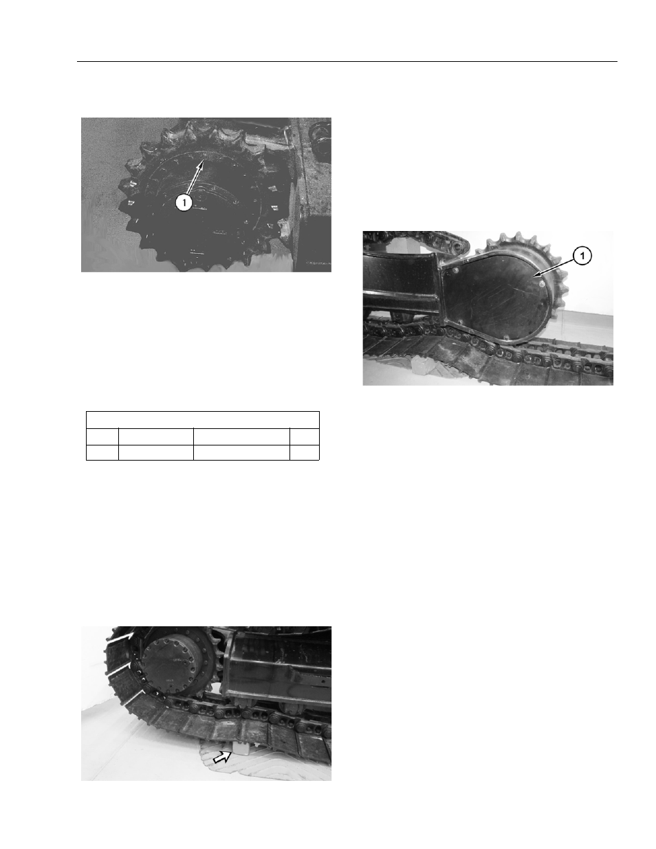
1.
Position the machine onto suitable cribbing below
the first roller, as shown. Ensure that the master pin
is above the center line of the sprocket.
2.
Release the hydraulic system pressure. Refer to
Section 4.2, System Pressure - Release.
3.
Remove the cap from the hydraulic tank. Install Tool-
ing (A) onto the hydraulic tank. Attach an air supply
hose to Tooling (A). Apply 276 to 414 kPa (40 to 60
psi) of air. This procedure will pull vacuum on the
hydraulic system.
4.
Separate the track assembly. Refer to Section 4.5,
Track.
5.
Remove cover assembly (1).
Table 4-15. Final Drive Required Tools - Removal
Required Tools
Tool
Part Number
Part Description
Qty.
A
FT-2674
Vacuum Cap
1