High drive speed cutout, 5 cylinder specifications, 6 major component weights – JLG 3248RS/10RS Service Manual User Manual
Page 17: 7 torque requirements, High drive speed cutout -5, Cylinder specifications -5, Major component weights -5, Torque requirements -5, High drive cutout height -5
SECTION 1 - SPECIFICATIONS
3121273
– JLG Lift –
1-5
level and above stowed depending on model and specifica-
tions.
High Drive Speed Cutout
High drive speed is cut out @ when the platform is raised
above the preset height per model as follows:
NOTE: These figures are given with a tolerance of ± 6 in.
(0.15 m).
1.5 CYLINDER SPECIFICATIONS
1.6 MAJOR COMPONENT WEIGHTS
1.7 TORQUE REQUIREMENTS
Self locking fasteners, such as nylon insert and thread
deforming locknuts, are not intended to be reinstalled
after removal. Always use new replacement hardware
when installing locking fasteners.
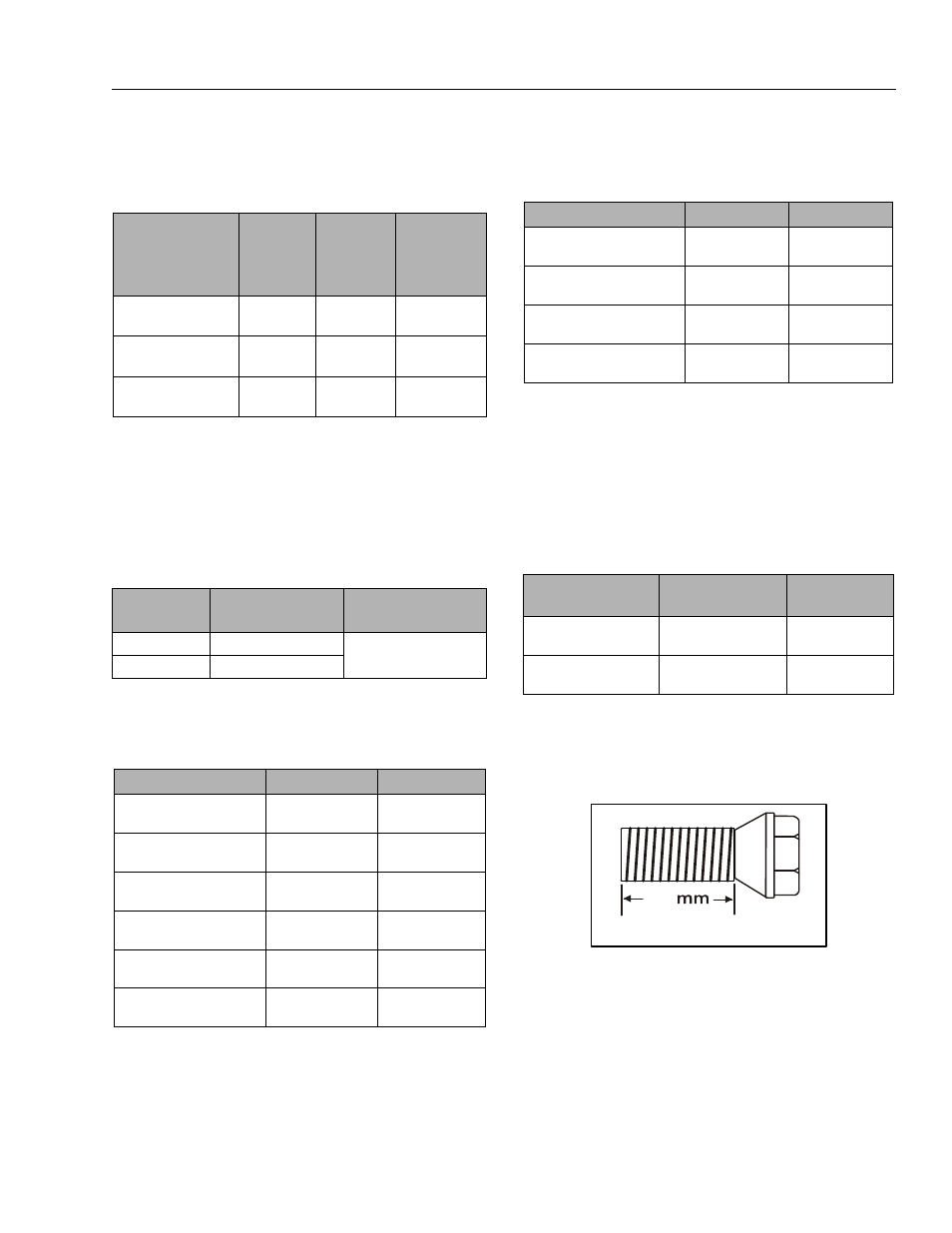
NOTE: Anytime a wheel bolt is replaced, be sure one of the
same length is used. Use bolt shown below on
wheels that use the 1/4" (6.4mm) ring.
NOTE: After tightening the spindle nut to the proper torque,
loosen completely until you can turn by hand. Finger
tighten nut by hand without rotating hub. Install cotter
pin by backing nut off, if necessary, in order to line up
slot.
When maintenance becomes necessary or a fas-
tener has loosened, refer to the Torque Charts on
page 1-6 to determine proper torque value.
Table 1-14. Tilt Activation Setting
MODEL
TILT
SETTING
(FRONT TO
BACK)
TILT
SETTING
(SIDE TO
SIDE)
PLATFORM
ELEVATION
@ TILT
ACTIVATION
(± 6 IN.)
1932RS/6RS - ALL
3°
1.5°
69 in.
(1.75 m)
3248RS/10RS -
ANSI/CSA/JPN
3°
2°
88.5 in.
(2.25 m)
3248RS/10RS - CE
3°
1.5°
88.5 in.
(2.25 m)
Table 1-15. High Drive Cutout Height
MODEL
HIGH DRIVE SPEED
CUTOUT HEIGHT
DRIVE SPEED
REDUCTION
1932RS/6RS
68.9 in. (1.75m)
2.5 mph (4 kph) to
0.3 mph (0.5 kph)
3248RS/10RS
88.5 in. (2.25 m)
Table 1-16. Cylinder Specifications
DESCRIPTION
1932RS/6RS
3246RS/10RS
Lift Cylinder Bore
2.48 in.
(63 mm)
3.93 in.
(100 mm)
Lift Cylinder Stroke
43.3 in.
(1100 mm)
48.5 in.
(1232 mm)
Lift Cylinder Rod Diameter
1.77 in.
(45 mm)
2.48 in.
(63 mm)
Steer Cylinder Bore
1.5 in.
(38.1 mm)
1.57 in.
(40 mm)
Steer Cylinder Stroke
4.92 in
(125 mm)
6.77 in.
(172 mm)
Steer Cylinder Rod Diame-
ter
0.75m in.
(19.05 mm)
0.78 in.
(20 mm)
Table 1-17. Major Component Weights
COMPONENT
1932RS/6RS
3246RS/10RS
Platform
240 lb.
(109 kg)
412 lb.
(187 kg)
Manual Platform Extension
115 lb.
(52 kg)
150 lb.
68 kg
Arm Assembly - (Includes
Lift Cylinder)
520 lb.
(236 kg)
1,806 lb.
(820 kg)
Chassis w/Wheel/Tire and
Drive Assembly
2,125 lb.
(964 kg)
2,702 lbs
(1226 kg)
Table 1-18. Torque Requirements
DESCRIPTION
TORQUE VALUE
(DRY)
INTERVAL
HOURS
Front Wheel Spindle Nut
30-40 ft lb
(40-54 Nm)
50
Wheel Bolts
105 -120 ft lb
(142-163 Nm)
50
M12 - 1.5 x 22
22