26— detailed cooling capacities* continued – Bryant SPLIT-SYSTEM 697C User Manual
Page 26
—26—
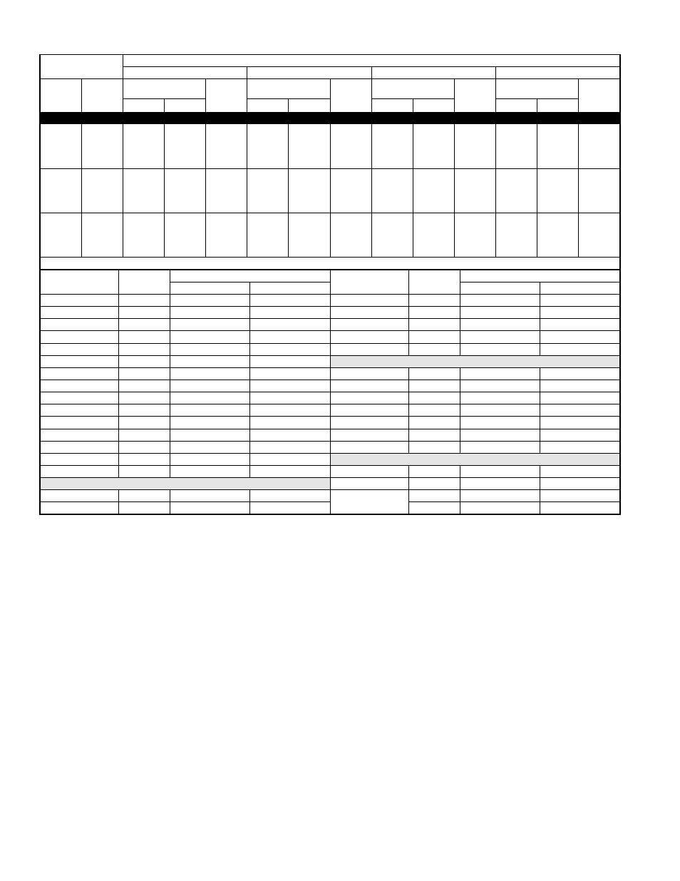
DETAILED COOLING CAPACITIES* Continued
* Detailed cooling capacities are based on indoor and outdoor unit at the same elevation per ARI standard 210/240-89. If additional tubing length and/or
indoor unit is located above outdoor unit, a slight variation in capacity may occur.
† Total and sensible capacities are net capacities. Blower motor heat has been subtracted.
‡ Sensible capacities shown are based on 80
°
F (27
°
C) entering air at the indoor coil. For sensible capacities at other than 80
°
F (27
°
C), deduct 835 Btuh
(245 kw) per 1000 CFM (480 L/S) of indoor coil air for each degree below 80
°
F (27
°
C), or add 835 Btuh (245 kw) per 1000 CFM (480 L/S) of indoor coil air
per degree above 80
°
F (27
°
C).
** System kw is total of indoor and outdoor unit kilowatts.
†† At TVA rating indoor condition (75
°
F edb/63
°
F ewb). All other indoor air temperatures are at 80
°
F edb.
EWB—Entering Wet Bulb
EVAPORATOR
AIR
CONDENSER ENTERING AIR TEMPERATURES
°
F
85
95
105
115
CFM
EWB
Capacity
MBtuh†
Total
System
Kw**
Capacity
MBtuh†
Total
System
Kw**
Capacity
MBtuh†
Total
System
Kw**
Capacity
MBtuh†
Total
System
Kw**
Total
Sens‡
Total
Sens‡
Total
Sens‡
Total
Sens‡
697C060-A Outdoor Section With FK4CNB006 Indoor Section
1575
72
66.2
32.7
4.89
63.3
31.7
5.42
60.2
30.5
6.0
57.0
29.4
6.63
67
61.0
41.4
4.82
58.4
40.3
5.35
55.5
39.2
5.9
52.5
38.0
6.54
63††
57.2
40.5
4.77
54.6
39.4
5.29
52.0
38.2
5.8
49.2
37.0
6.47
62
56.2
49.9
4.76
53.7
48.7
5.28
51.1
47.5
5.8
48.4
46.2
6.46
57
54.0
54.0
4.73
52.1
52.1
5.26
50.1
50.1
5.8
47.8
47.8
6.45
1750
72
67.0
33.9
4.95
64.1
32.9
5.49
60.8
31.7
6.0
57.5
30.5
6.69
67
61.8
43.4
4.89
59.0
42.3
5.41
56.1
41.2
5.9
53.0
39.9
6.61
63††
57.9
42.4
4.84
55.3
41.2
5.36
52.6
40.0
5.9
49.7
38.8
6.54
62
57.1
52.7
4.83
54.5
51.5
5.35
51.9
50.1
5.9
49.2
48.7
6.53
57
55.7
55.7
4.81
53.6
53.6
5.34
51.4
51.4
5.9
49.0
49.0
6.53
2012
72
67.8
35.6
5.05
64.7
34.5
5.58
61.5
33.3
6.1
58.0
32.2
6.79
67
63.1
46.5
4.99
60.2
45.4
5.52
56.8
44.0
6.0
53.6
42.8
6.70
63††
58.8
45.1
4.93
56.1
43.9
5.45
53.3
42.7
6.0
50.2
41.5
6.64
62
58.5
56.7
4.93
55.6
55.1
5.45
53.1
53.1
6.0
50.6
50.6
6.65
57
57.7
57.7
4.92
55.5
55.5
5.45
53.2
53.2
6.0
50.7
50.7
6.65
Multipliers for Determining the Performance With Other Indoor Section
s
Indoor
Section
Size
Cooling
Indoor
Section
Size
Cooling
Capacity
Power
Capacity
Power
F(A,B)4AN(F,B,C)
060
0.97
1.06
CD3(A,B)A
060
0.94
1.01
FB4ANB
070
0.99
1.04
CE3AA
060
0.97
1.01
FC4BN(F,B)
060
0.97
1.06
CJ5A/CK5A/CK5BA
060
0.97
1.00
FC4BNB
070
0.99
1.04
CJ5A/CK5A/CK5BX
060
0.99
0.99
FG3AAA
060
0.96
1.02
CK3BA
060
0.97
1.00
FK4BNB
006
1.00
1.01
COILS + 333(B,J)AV060120 VARIABLE-SPEED FURNACE
FK4CNB
006
1.00
1.00
CC5A/CD5A/CD5BA
060
0.93
1.02
CC5A/CD5A/CD5BA
060
0.94
1.02
CC5A/CD5A/CD5BW
060
0.96
1.01
CC5A/CD5A/CD5BW
060
0.96
1.02
CD3(A,B)A
060
0.93
1.02
CD3(A,B)A
060
0.94
1.02
CE3AA
060
0.97
1.02
CE3AA
060
0.97
1.03
CJ5A/CK5A/CK5BA
060
0.97
1.01
CJ5A/CK5A/CK5BA
060
0.97
1.02
CJ5A/CK5A/CK5BX
060
0.98
1.00
CJ5A/CK5A/CK5BN
060
0.97
1.02
CK3BA
060
0.97
1.01
CJ5A/CK5A/CK5BX
060
0.98
1.02
COILS + 355MAV060100 VARIABLE-SPEED FURNACE
CK3BA
060
0.97
1.02
CC5A/CD5A/CD5BA
060
0.93
1.04
COILS + 333(B,J)AV060100 VARIABLE-SPEED FURNACE
CC5A/CD5A/CD5BW
060
0.96
1.04
CC5A/CD5A/CD5BA
060
0.94
1.01
CD3(A,B)A
060
0.93
1.04
CC5A/CD5A/CD5BW
060
0.97
1.00
—
—
—