11 brake cylinder repair, Disassembly, Brake cylinder repair -8 – JLG 3246E2 ANSI Service Manual User Manual
Page 22: Cylinder component torque specifications -8, Holding valve torque specifications -8
SECTION 2 - PROCEDURES
2-8
– JLG Lift –
3120737
WHEN INSTALLING NEW “PARKER” TYPE PISTON SEALS,
ENSURE SEALS ARE INSTALLED PROPERLY. IMPROPER SEAL
INSTALLATION COULD RESULT IN CYLINDER LEAKAGE AND
IMPROPER CYLINDER OPERATION.
2. Using a soft mallet, tap a new wiper seal into the
applicable cylinder head gland groove. Install a new
wear ring into the applicable head gland groove as
shown below.
3. Place a new o-ring and back-up seal in the applica-
ble outside diameter groove of the cylinder head.
4. Install a washer ring onto the rod, then carefully
install the head gland on the rod, ensuring that the
wiper and rod seals are not damaged or dislodged.
Push the head along the rod to the rod end, as
applicable.
5. Carefully slide the piston spacer onto the rod.
6. If applicable, correctly place a new o-ring and back-
up rings in the inner piston diameter groove.
7. Using suitable protection, clamp the cylinder rod in
a vise or similar holding fixture as close to the piston
as possible.
8. Carefully place the piston on the cylinder rod, ensur-
ing that the o-ring and back-up rings are not dam-
aged or dislodged.
9. Place the piston onto the rod until it abuts the spacer
end and install the seal and guidelock ring.
10. Place the locknut on the end of the cylinder rod and
tighten.
11. Remove the cylinder rod from the holding fixture.
12. Thoroughly rinse the inside of the rod weldment and
allow to drain. Wipe with a lint free rag.
EXTREME CARE SHOULD BE TAKEN WHEN INSTALLING THE
CYLINDER ROD, HEAD, AND PISTON. AVOID PULLING THE ROD
OFF-CENTER, WHICH COULD CAUSE DAMAGE TO THE PISTON
AND CYLINDER BARREL SURFACES.
13. Clean and visually inspect all parts for material
defects and contamination.
14. Lubricate the head, piston, and all seals with hydrau-
lic fluid prior to installation.
15. When the rod is ready to be installed in the rod weld-
ment, liberally apply an anti-seize lubricant to the
head outer surface.
16. Cover the entire rod assembly with hydraulic fluid
and, with the rod weldment positioned in a suitable
holding fixture, insert the rod into the rod weldment.
17. Using a spanner wrench tighten the cylinder head.
18. After the cylinder has been reassembled, the rod
should be pushed all the way in (fully retracted) prior
to the reinstallation of any holding valve or valves.
19. If applicable, install the cartridge-type holding valve
and fittings in the port block using new o-rings as
applicable. Refer to Table 2-2 for proper holding
valve torque specifications.
NOTE: The following holding valve torque values are for the
valve cartridge only.The solenoid nut should be
torqued to 5 ft lb (6.8 Nm) on all models.
2.11 BRAKE CYLINDER REPAIR
Disassembly
DISASSEMBLY OF THE CYLINDER SHOULD BE PERFORMED ON
A CLEAN WORK SURFACE IN A DIRT FREE WORK AREA.
1. Tag and disconnect the hoses from the cylinder
ports.
DO NOT FULLY EXTEND CYLINDER TO END OF STROKE.
RETRACT CYLINDER SLIGHTLY TO AVOID TRAPPING PRES-
SURE.
2. Place the cylinder barrel into a suitable holding fix-
ture.
3. Using a suitable pair of snap ring pliers, carefully
remove the retaining ring from the cylinder barrel.
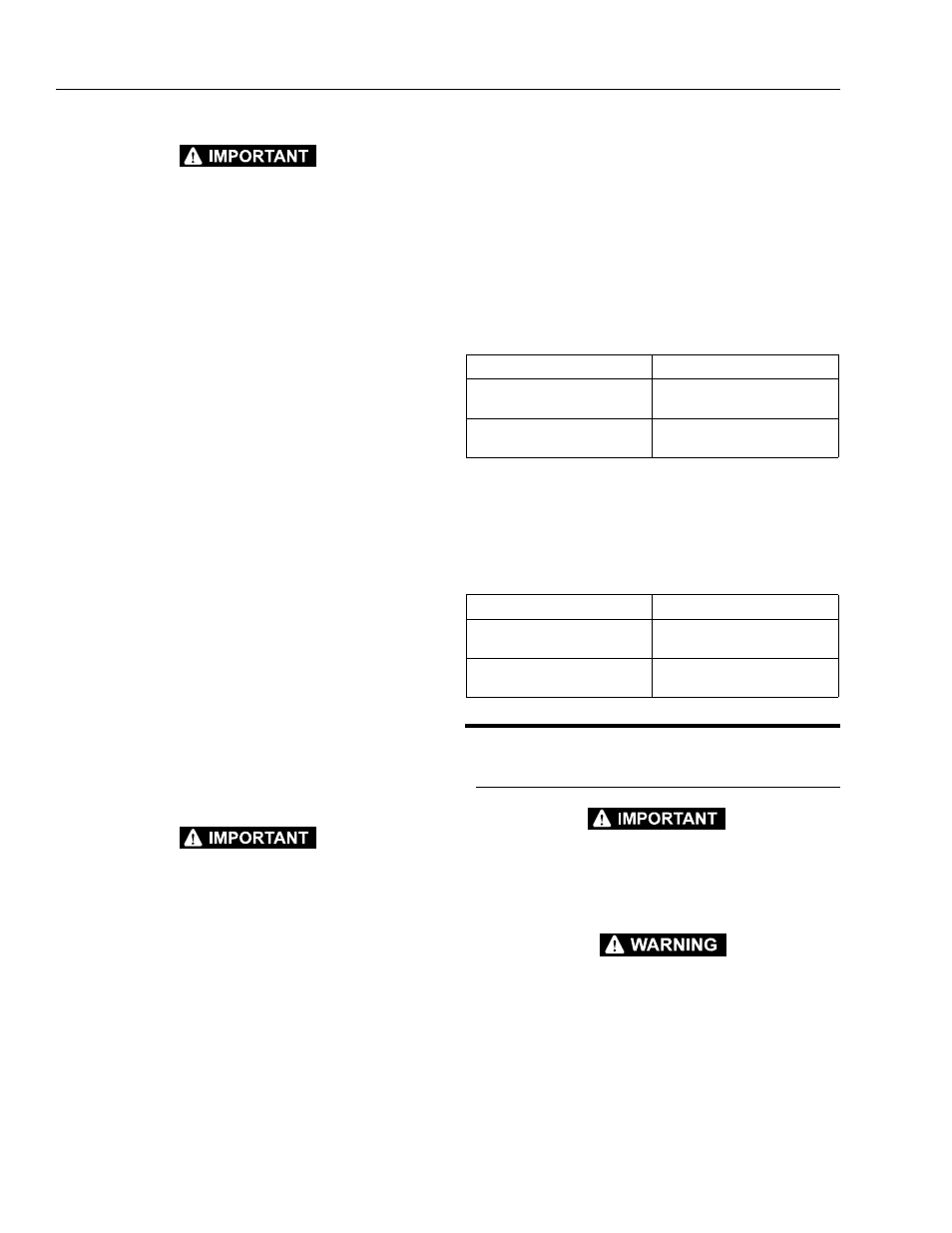
Table 2-1. Cylinder Component Torque Specifications
Component
Torque Value (w/Loctite)
Piston Nut - Lift Cylinder 1532E2/
1932E2
375-450 ft lb
(508-610 Nm)
Piston Nut - Lift Cylinder 2032E2/
2632E2/2646E2/3246E2
800-1000 ft lb
(1085-1356 Nm)
Table 2-2. Holding Valve Torque Specifications
Description
Torque Value
1532E2/1932E2/2032E2 -
Hydraforce - 1.25" hex 3/4 - 16 thds
20 ft lb
(27.1 Nm)
2632E2/2646E2/3246E2 -
Hydraforce - 1" hex 7/8- 14 thds
25 ft lb
(33.9 Nm)