9 hose adjustment procedure, Hose adjustment procedure -6, Hose adjustment - figure 1 -6 – JLG 18RS Service Manual User Manual
Page 86: Hose adjustment - figure 2 -6, Hose pull order -6
SECTION 4 - BOOM & PLATFORM
4-6
– JLG Lift –
3121284
4.9 HOSE ADJUSTMENT PROCEDURE
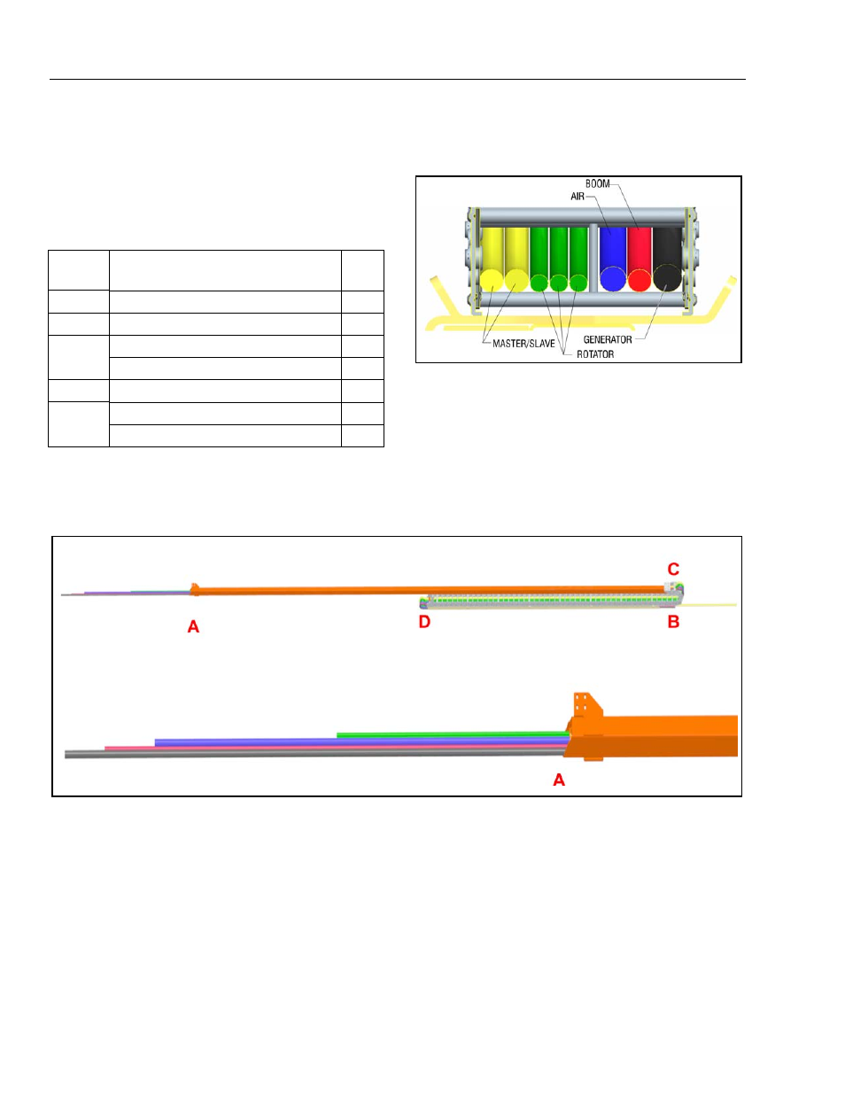
1. Starting at the front of the machine, pull the hoses
and cables in the order shown in Table 4-1. Hose
Pull Order, through the carrier tube (Figure 4-5.,
Hose Adjustment - Figure 3, location B).
2. Pull the hoses and cables through the power track in
the same order as through the carrier tube. Position
the hoses and cables in the power track as noted in
the assembly drawings. Note the orientation of the
marking on the hoses and cables to insure there is
no twist. (See Figure 4-3., Hose Adjustment - Figure
1 below).
3. Pull the hoses and cables through the push tube in
the same order as the carrier tube and power track.
4. Adjust the pull lengths at position “A” (See Figure 4-
4., Hose Adjustment - Figure 2). With the pull
lengths set, tighten the hose clamp at position “A”
until hoses are tight and unable to be moved.
5. Adjust the pull lengths at position “B” (See Figure 4-
5., Hose Adjustment - Figure 3). With the pull
Table 4-1. Hose Pull Order
Pull
Order
Description
Qty
1
Control Cable, Upper Boom
1
2
Hose, 1/2" Airline (optional)
1
3
Cable, A/C 10/3 Upper Boom
1
Cable, 8/5 Upper Boom (optional)
1
4
Hose Assy, 10 [.375] JIC/JIC
2
5
Hose Assy, 6 [.25] JIC/JIC
2
Hose Assy, 6 [.25] JIC/JIC
1
Figure 4-3. Hose Adjustment - Figure 1
Figure 4-4. Hose Adjustment - Figure 2