Installation instructions, Removing propeller assembly from shaft – Aerovent IM-170 User Manual
Page 2
Aerovent adjustable pitch propellers are furnished with
hubs that have a tapered bore. A split taper bushing is
used for mounting the propeller assembly to the shaft.
When properly assembled, the bushing grips the hub
and the shaft with a positive clamping action. The split
taper bushing is always mounted on the discharge or
cap side of the hub unless the propeller has been
ordered with a reverse bore.
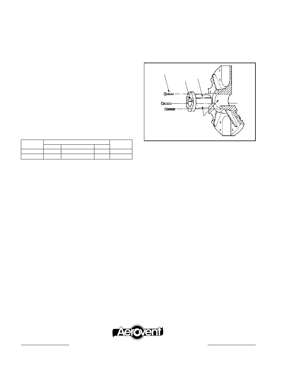
A. Bushing barrel and bore of propeller hub are
tapered. This assures concentric mounting and a
true running propeller.
B. Capscrews, when tightened, lock bushing in propel-
ler. Use plated capscrews threaded full length (see
table below).
C. Bushing is split so that when the locking capscrews
force bushing into tapered bore, the bushing grips
the shaft with a positive clamping fit. This will with-
stand vibration and punishing loads without being
loosened.
D. Propeller and bushing assembly is keyed to shaft
and held in place by compression. This gives added
driving strength.
Installation Instructions
Put bushing loosely into propeller. Do not press or
drive. Start capscrews by hand, turning them just
enough to engage threads in tapped holes on propel-
ler. Do not use a wrench at this time. The bushing
should be loose enough in the propeller to move
slightly.
Be sure shaft and keyway are clean and smooth.
Check key size with both shaft and bushing keyways.
Slide propeller and bushing assembly onto shaft, mak-
ing allowance for end play of shaft to prevent rubbing.
Do not force propeller and bushing onto shaft. If it
does not go on easily, check shaft, bushing and key
sizes.
Tighten capscrews progressively with wrench. Do
this evenly as in mounting an automobile wheel. Take
a part turn on each capscrew successively until all are
tight.
These capscrews force the taper bushing into the
hub which in turn compresses the bushing onto the
shaft. This makes a positive clamping fit. The torque
must not exceed 24 ft. lbs. for Q bushings and for R
bushings.
WARNING: Do not attempt to pull bushings flange
flush with hub end. There should be
1
∕
8
" to
1
∕
4
" clear-
ance when tightened.
Removing Propeller Assembly From Shaft
Propeller is easily removed from shaft by inserting and
tightening two of the capscrews into the tapped holes
in the bushing flange. This forces the bushing loose
from the propeller and releases the compression so
that the entire assembly will slide from the shaft.
1. Remove all three capscrews from propeller and hub
assembly.
2. Start capscrews into the threaded holes in the
bushing flange.
3. Tighten each bolt part of a turn successively to
force the propeller off the bushing.
4. Pull the bushing off the shaft. If the assembly has
been in place some time, it may be necessary to
use a wheel puller to remove the bushing. Never
use a wheel puller on the propeller.
For propeller dimensions, see drawing R-9183.
Installation Instructions For Propellers Equipped With
Browning Malleable Iron Split Taper Bushings
B
D
C
A
DO NOT LUBRICATE
CAPSCREWS, BORE, OR
BUSHING BARREL.
Right-hand or left-hand rotation of propellers is determined as follows: When facing into the discharge of
the fan, clockwise rotation is right-hand; counterclockwise rotation is left-hand. The thicker rounded edge of the
blade or edge opposite the pointed tip is the leading edge.
BUSH
CAPSCREW
TORQUE
NO.
SIZE
THREADS/IN
LENGTH
(FT/LBS)
Q2
3
∕
8
"
16
2
1
∕
2
"
24
R2
3
∕
8
"
16
3"
24
2MWG12/11
www.aerovent.com
5959 trenton Lane n | minneapolis, mn 55442 | Phone: 763-551-7500 | Fax: 763-551-7501
®