Wheel clearance, Maintenance, Type bw, ow, pb & hpb – Aerovent IM-140 User Manual
Page 2: Type aw, Type fc, Type biub
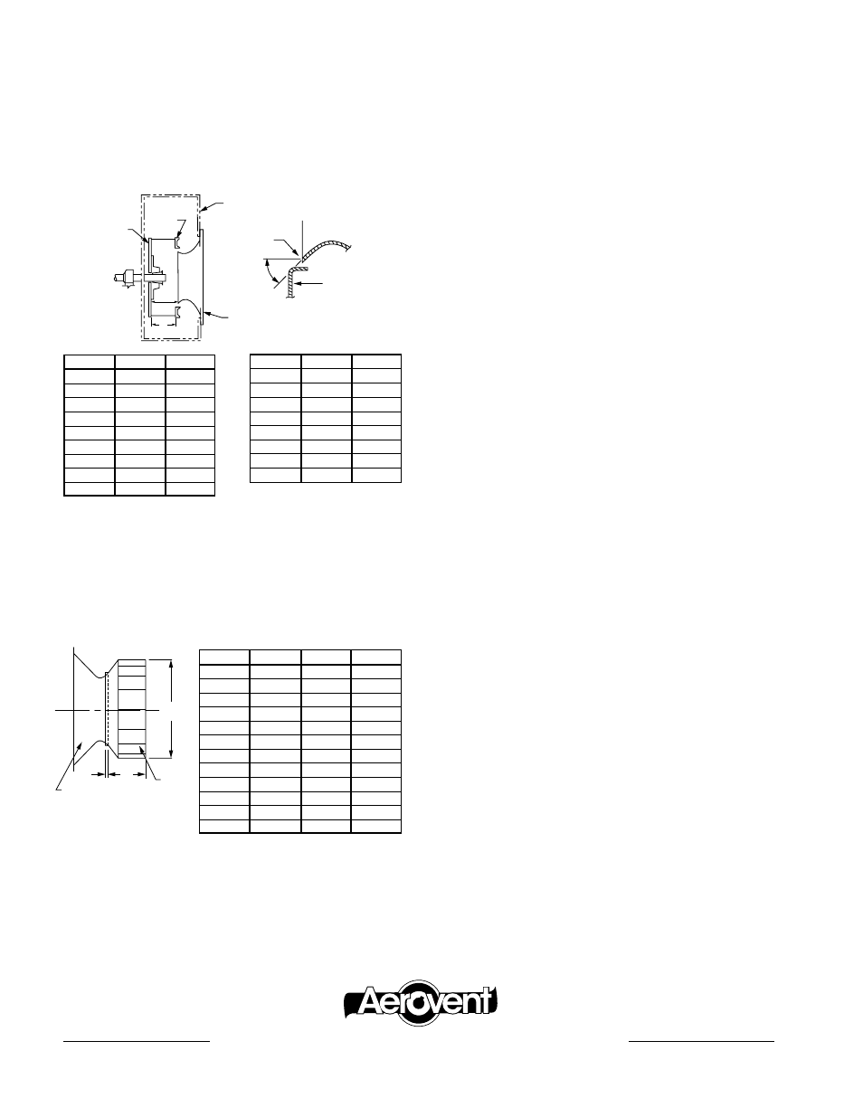
Wheel Clearance
Adjust clearance by moving the wheel axially on the shaft. The
following table indicates the correct measurements for position-
ing the BI and BIA wheels. Proper positioning is important in
attaining correct fan performance, particularly on the BI and
BIA wheels.
Type BW, OW, PB & HPB
These radial blade wheels do not require precise positioning
to attain the correct performance. The important thing is to
centrally locate these wheels axially within the housing to ensure
adequate running clearance and to maintain concentricity with
the fan inlet.
Type AW
These wheels require a special inlet on the housing which must
extend into the wheel inlet flange to perform properly. Other
than maintaining a minimum
1
∕
4
" overlap, adequate running
clearance and concentricity are all that is required.
Type FC
The forward curve blower employs a shallow venturi in the
housing to guide the air into the wheel. The depth of this ven-
turi is approximately one-tenth the wheel diameter. Clearance
between the wheel and venturi should be the smallest allowable
and still maintain normal running clearance. This axial separa-
tion is approximately
1
∕
4
" and should be measured at four points
approximately 90° apart.
Maintenance
Regular and systematic inspection of all fan parts is the key to
good fan maintenance. Frequency of inspection is determined
by the severity of the application and local conditions. Once a
maintenance schedule is established, it should be strictly fol-
lowed. Regular fan maintenance should include the following:
1. Check fan wheel for any build-up of foreign material or
excessive wear from abrasion. Both can cause vibration
which creates a serious safety hazard. Any build-up of for-
eign material should be removed. If the wheel shows exces-
sive wear, replace it immediately.
2. On belt driven units, check V-belt drive for proper alignment
and tension. If belts show wear, they should be replaced with
a matched set of belts. If unit is direct driven, check coupling
alignment.
3. Lubricate the bearings (see bearing section for lubrication
specifications). On direct drive units, lubricate the coupling
(see coupling section).
4. Lubricate shaft seal with the same grease as used on the fan
bearings. IMPORTANT: The operating life of the shaft seal
is dependent upon the amount and frequency of lubrication.
Insufficient grease in the shaft seal may result in damage to
the seal and reduced sealing efficiency.
5. A final check on the tightness of all setscrews and bolts
completes the maintenance routine.
SIZE
A
W*
12
4
11
/
16
4
7
/
16
14
5
9
/
32
5
1
/
32
16
5
29
/
32
5
21
/
32
18
6
23
/
32
6
3
/
8
20
7
7
/
16
7
1
/
16
22
8
5
/
16
7
15
/
16
25
9
5
/
16
8
15
/
16
28
10
17
/
32
10
1
/
16
32
11
27
/
32
11
11
/
32
SIZE
A
W*
35
13
15
/
16
12
3
/
4
39
14
27
/
32
14
3
/
16
44
16
9
/
16
15
7
/
8
49
18
9
/
16
17
23
/
32
55
20
7
/
8
19
27
/
32
63
23
3
/
4
22
11
/
16
71
26
19
/
32
25
1
/
2
79
29
5
/
8
28
11
/
32
Wheel Front
Plate
Inlet
Cone
Wheel/Cone
Geometry
Housing
45°
Inlet
Cone
Front
Plate
Wheel
Back Plate
A
W
*100% Wheel Width
“A” dimension (inside edge of inlet cone to inside face of
wheel backplate) must be held. This dimension is critical to fan
performance. “A” dimension shown is based on 100% wheel
width “W” and must be adjusted if wheel furnished is other
than 100% full width.
Type BIUB
B
A
DIA.
C
Inlet Cone
Wheel
SIZE
A
B
C
12
12.25
0.32
4.28
13
13.50
0.34
4.84
15
15.00
0.38
5.38
16
16.50
0.44
5.81
18
18.25
0.56
6.44
20
20.00
0.63
7.00
22
22.25
0.69
7.84
24
24.50
0.75
8.63
27
27.00
0.88
9.47
30
30.00
0.97
10.56
33
33.00
1.06
11.63
36
36.50
1.10
13.03
3MSE09/09
Type BI & BIA (SWSI Units)
Aerovent | www.Aerovent.com
5959 trenton Lane n | minneapolis, mn 55442 | Phone: 763-551-7500 | Fax: 763-551-7501
®