Installation, Table 1. utilization voltages, Check, test & start procedure – Aerovent IM-435 User Manual
Page 2: Warning
2
Aerovent IM-435
Installation
Roof ventilators should always be mounted to a flat,
level, solid and rigid structure. Particular caution should
be exercised when installing fans on metal buildings. Be
sure wall or roof is capable of supporting the fan(s).
Fans mounted on walls or roofs and not supported
correctly will cause vibration that could cause damage
or injury.
Fans mounted off ground level should be rigidly mount-
ed to a structural platform and be placed over or as
near as possible to a solid wall or column.
Support for suspended fans must be cross-braced for
live load support to prevent side sway.
Use guy wires to help secure roof units if excessively
windy conditions prevail.
1. CAUTION! This fan contains rotating parts and
requires electrical service. Appropriate safety precau-
tions should be taken during installation, operation
and maintenance.
2. WARNING! Do not install or operate this fan in an
environment or atmosphere where combustible or
flammable materials, gasses or fumes are present
unless it was specifically designed and manufac-
tured for use in that environment. Explosion or fire
can result. Explosive, corrosive, high temperature,
or other extreme conditions may require special
construction, inspection and maintenance. It is
necessary to observe the fan manufacturer’s recom-
mendations and limitations concerning the type of
material to be handled by the fan and its application
to special conditions.
3. When the roof ventilator is designed to be mounted
on a curb, the curb should be securely installed
prior to fan installation.
4. A damper, if used, should be securely mounted
within the curb or wall in a manner which allows
free and unobstructed operation.
5. CAUTION! All electrical work must be done in accor-
dance with local and/or national electrical codes as
applicable. If you are unfamiliar with methods of
installing electrical wiring, secure the services of a
qualified electrician.
6. WARNING! This product must be grounded.
7. DANGER! Make sure power is turned off and locked
in the OFF position at the service entrance before
installing, wiring or servicing fan.
8. CAUTION! Before wiring the motor, check the sup-
ply voltage against the motor nameplate voltage.
High or low voltage can damage the motor and void
the motor warranty. See Table 1.
9. On three-phase units check and calculate phase
unbalance as follows:
% Voltage Unbalance = 100 x max. voltage deviation
from avg. voltage ÷ avg. voltage
How To Use The Formula:
With voltage of 220, 216 and 213
a. Avg. Voltage = 220 + 216 + 213 = 649 ÷ 3 = 216
b. Max. Voltage Deviation From Avg. Voltage =
220 – 216 = 4
c. % Voltage Unbalance = 100 x (4 ÷ 216) = 1.8%
Voltage unbalance should not exceed 2%.
10. WARNING! Be sure to keep all wiring clear of rotat-
ing or moving parts.
11. WARNING! Before starting the fan, turn the wheel to
assure it rotates freely. If needed, adjust the wheel/
shaft/bearing/motor position as required to achieve
necessary clearances.
12. On belt driven units, assure belts are tensioned and
aligned properly. See Maintenance section, page 3.
13. Check all setscrews and keys. Tighten as necessary
prior to fan start-up.
14. On roof units, anchor the fan securely to the curb.
Anchoring through the vertical portion of the curb
cap flange is recommended. Use a minimum of four
lag bolts or other suitable fasteners.
15. As with most installations of rotating machinery,
due to the nature of their applications, most fans
are available with protective guards and/or other
devices for required operating safety. Before operat-
ing the unit in any of its applications, determine the
requirements for any guards and/or devices needed
for protection against accidental contact with mov-
ing parts or against injury to nearby personnel or
equipment due to accidental rupture of fast moving
parts.
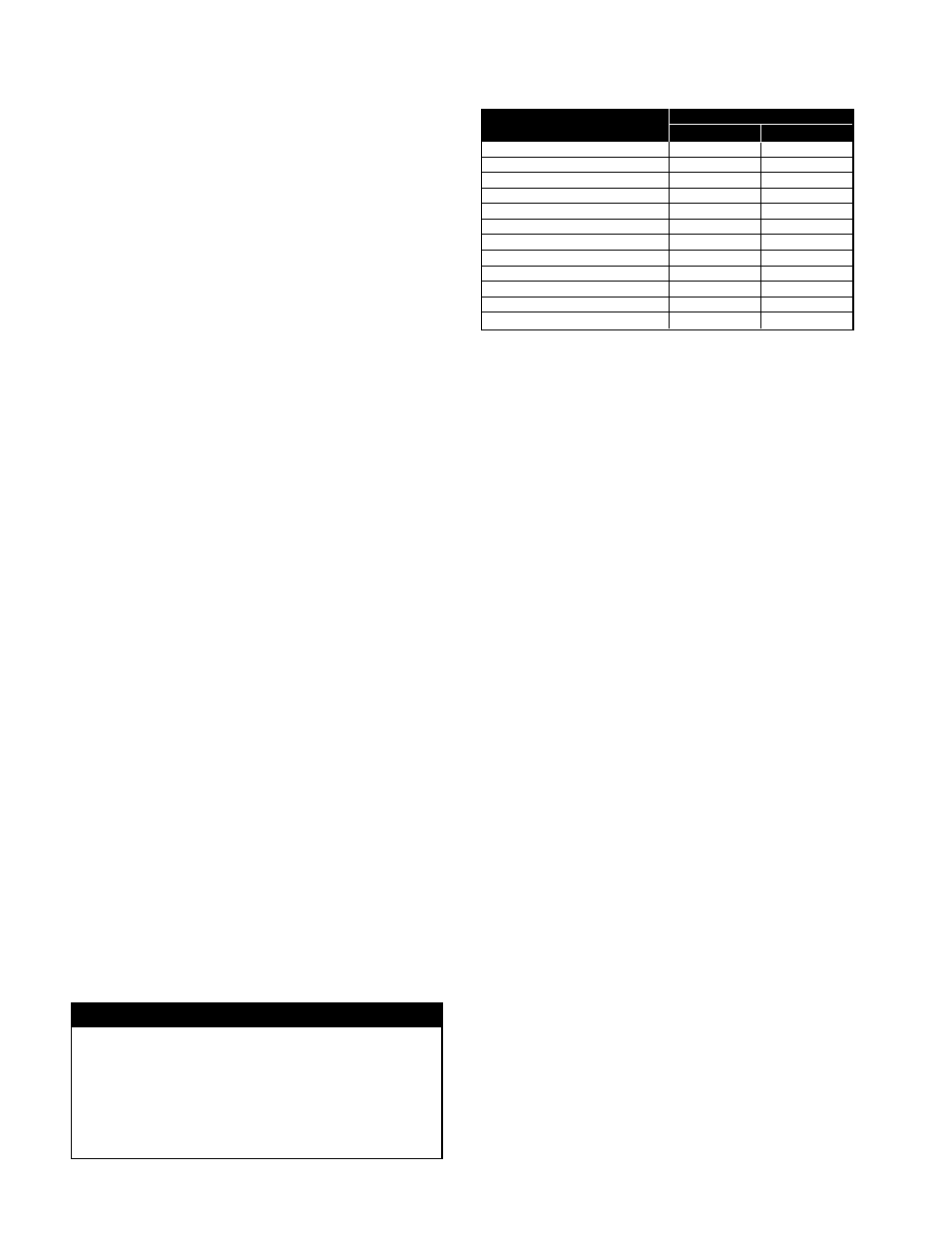
Table 1. Utilization Voltages
SYSTEM VOLTAGE/
UTILIZATION VOLTAGE
UNIT NAMEPLATE
MIN.
MAX.
115/60/1
104
127
208-230/60/1 or 208-230/60/3
187
253
230/60/1 or 230/60/3
207
253
277/60/1
249
305
200/60/3
180
220
380/60/3
342
418
460/60/3
414
506
575/60/3
517
633
110/50/1
99
121
220/50/1
198
242
380-415/50/3
342
456
440/50/3
396
484
Check, Test & Start Procedure
WARNING
Electric shock hazard. Could cause severe injury or
death. Failure to bond the frame of this equipment
to the building electrical ground by use of the
grounding terminal provided or other acceptable
means may result in electrical shock.
Disconnect
electric power before servicing equipment. Service
to be performed only by qualified personnel.
BEFORE START-UP: Disconnect power to this unit
before servicing the unit.
1. Check to verify that the propeller is free to rotate.
2. Verify that supply voltage on the line side of discon-
nect agrees with voltage on fan data plate and is
within the 10% utilization voltage.
3. Apply power to unit and check rotation of propeller
with the directional arrow on the unit.
WARNING: Rotation is critical. If allowed to operate
in the wrong direction, the motor will overload and
burn out.