Aries Automotive P1050 User Manual
Page 5
Page 4 of 5
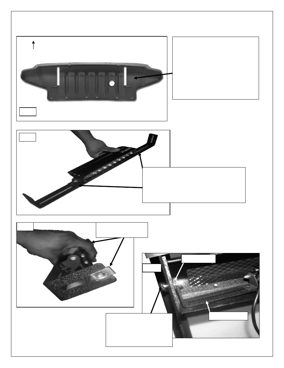
Driver Side Installation Pictured
Fig 7
Once the Mounting Brackets have
been installed and checked for
alignment, hold the splash guard up
into position and mark the cut area
on the inside of the guard. Start with
a small opening and slowly enlarge
the opening to get the best fit around
the brackets. Area cut from guard
pictured for example only.
(Interior view)
Front
Fig 8
LED light attached to support flange.
NOTE:
LED Manufactures will have similar
but different mounting styles or brackets,
once you determine you mounting options
attach it to the support flange as seen.
8mm nut clip
attached (1) per side
Fig 9
Support flange
8mm nut clip
Secure support flange into
center flange with
(1) 8mm Button head bolt
(1) 8mm Flat Washers
(1) 8mm Lock washer
Per side.
Fig 10
- 4049 (1 page)
- 4066 (2 pages)
- 4052 (2 pages)
- 4059 (2 pages)
- 4065 (2 pages)
- 4044 (1 page)
- 4080 (3 pages)
- 4042 (1 page)
- 4047 (1 page)
- 4068 (2 pages)
- 4083 (9 pages)
- 4057 (1 page)
- 4060 (2 pages)
- 4050-2 (4 pages)
- 4061 (2 pages)
- 4069 (2 pages)
- 4081 (3 pages)
- 4043 (2 pages)
- 4051-2 (4 pages)
- 5041 (1 page)
- 5052 (4 pages)
- 5047 (2 pages)
- 5053-2 (2 pages)
- 5057 (3 pages)
- 5042 (1 page)
- 5050 (2 pages)
- 5058 (7 pages)
- 5046 (2 pages)
- 5049 (2 pages)
- 5056 (2 pages)
- 3049 (2 pages)
- 3058 (1 page)
- 3062 (5 pages)
- 3045 (2 pages)
- 3057 (2 pages)
- 3042F (1 page)
- 3046 (2 pages)
- 3046F (3 pages)
- 2003-05 (2 pages)
- 3060 (2 pages)
- 3047 (2 pages)
- 3052 (2 pages)
- 3059 (4 pages)
- 3065 (8 pages)
- 3048 (1 page)