Caution – Snorkel TB126J CE User Manual
Page 25
Chapter 6 – Controls
TB126J – 0192117EE
21
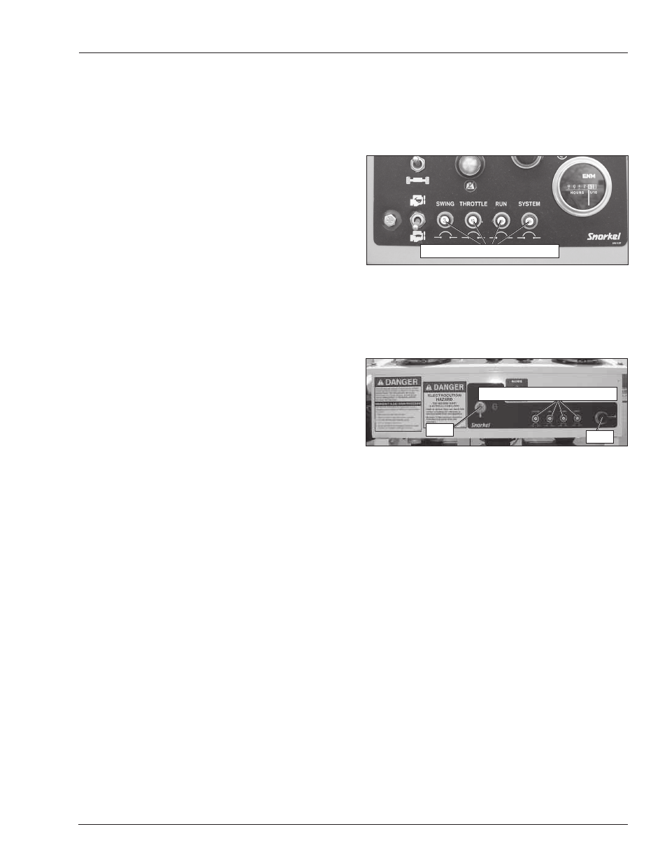
Circuit Breaker Reset Buttons
The lower control panel electrical system has a circuit
breaker for the lift/swing, throttle, run and main circuits
(refer to Figure 6.5). There is a reset button for the circuit
breaker on the bottom of the lower control panel.
Figure 6.5 – Lower Controls
The upper control panel (refer to Figure 6.6) has a cir-
cuit breaker for the lift, swing, main and drive circuits.
The circuit breaker reset buttons are on the front of the
upper control panel.
Figure 6.6 – Upper Control Panel Front
The circuit breakers protect the electrical wiring and
components from electrical overload in case of a short
circuit or other fault.
A
Caution
A tripped circuit breaker indicates a malfunction in
the electrical system. Component damage can result
if the cause of the malfunction is not corrected. Do
not operate the aerial platform if the circuit breaker
trips repeatedly.
Push the button to reset the circuit breaker.
Upper Controls
The upper controls (refer to Figure 6.7) are located on
the control panel at the platform. Boom, platform and
drive functions can be operated from the upper controls.
The following controls are located on the upper control
panel.
Start switch
Emergency stop button
Drive/boom selector switch
Boom joystick
Drive joystick
Drive range switch
Platform Rotate Switch
The platform rotator switch is used to rotate the platform
relative to the end of the tip boom. The switch is spring
returned to the center off position.
Hold the switch to the right to rotate the platform coun-
terclockwise. Hold the switch to the left to rotate the
platform clockwise.
Engine/Emergency Power Switch
Hold the engine/emergency power switch down to oper-
ate aerial platform functions using the emergency power
system. Release the switch to disengage the emergency
power system.
Note
The emergency power system is for lowering the plat-
form during an emergency and is not intended for normal
machine operation.
If the engine is running, it will stop when the switch is
placed in the emergency power position.
Throttle Switch
The throttle switch (refer to Figure 6.4) is used to set the
engine throttle speed in either low or high idle.
Place the switch in the low position before starting the
engine and in the high position for machine operation
and for engine and/or hydraulic system warm-up.
The engine has a two speed throttle operation from the
lower controls. When the throttle switch is in the low posi-
tion the engine is at idle. Placing the switch in the high
position increases the engine speed to mid-range.
Placing the ground controls switch in the on position also
increases the engine speed to mid-range.
Hydraulic System Warm-Up Switch
Some units may have an optional hydraulic fluid warm-
up system. This system may be used to warm the
hydraulic fluid when the ambient temperature is below
0°C (32°F) and boom movement is sluggish because
of cold fluid.
There is a toggle switch for the warm-up system on the
lower control panel and one on the left side of the upper
control panel.
The engine must be running and the switch used to turn
the system on, must be at the same location that the en-
gine was started. For example, if the engine was started
from the lower controls, the warm-up switch at the lower
controls must be used for the system to operate.
Machine functions are not operational while using the
hydraulic warm-up system.
Circuit Breaker Reset Buttons
Circuit Breaker Reset Buttons
Horn
Start