Upper control station 8-8, Guardrail system 8-8, Platform extension 8-8 – Snorkel S2033 User Manual
Page 32: Operating controls 8-8, Guardrail system, 8-8, Mid rail, 8-8, Removable top rail, 8-8, Safety chain, 8-8, Swinging gate, 8-8, Toeboards, 8-8
■
Upper Control Station
Inspect the platform and upper controls only if all
functions operated properly from the lower
controls.
❑
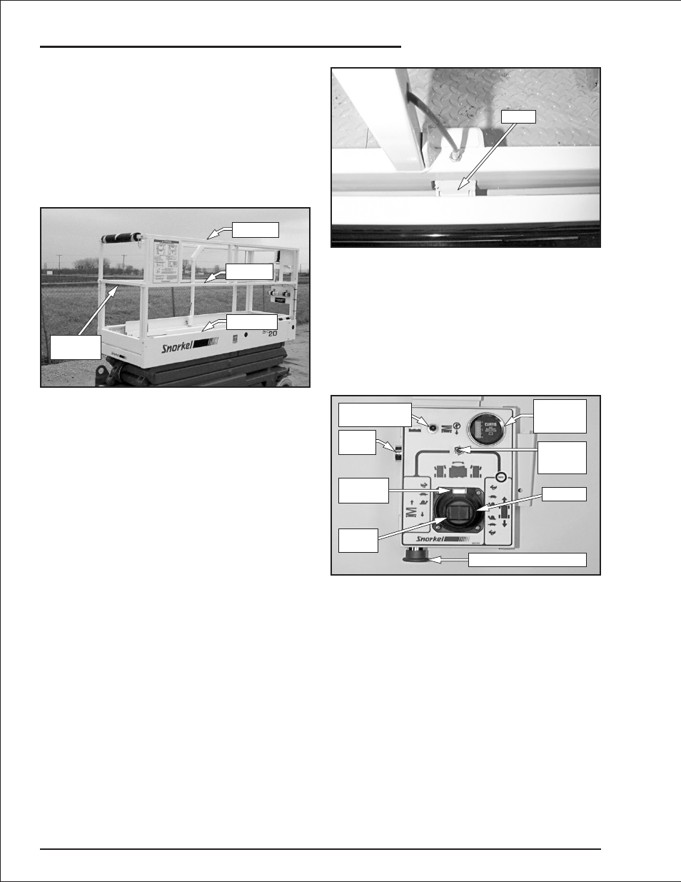
Guardrail System
The guardrail system (refer to Figure 8.20)
includes the top rail, mid rail, toeboards and a
safety chain or optional swinging gate.
Figure 8.20—Guardrail System
Inspect all components of the guardrail system.
The rails and toeboards must all be in place and
free of any damage or deformation. Visually
check the rail and toeboard welds for cracks. All
bolts and nuts fastening the guardrails in place
must be present and not show any signs of
looseness.
Inspect the removable top rail at the platform
entrance to be sure it is present and securely
fastened to the rail. The removable rail must be
free of damage and deformation that may prevent
if from functioning properly. Inspect the fastener
that secures the rail.
Inspect the safety chain to be sure it is present
and securely fastened to the rail. The chain must
be free of damage and deformation that may
prevent if from functioning properly. Inspect the
hook and eye that secures the chain to the rail.
Inspect the swinging gate to see that it swings
freely, closes firmly, and is not deformed in any
way. Make sure the latch closes and secures the
gate when the gate is closed.
❑
Platform Extension
Inspect the extension latch (refer to Figure 8.21)
to ensure that it properly secures the extended
platform. The latch must also release to extend
the platform. Extend the platform while checking
for proper operation.
Figure 8.21—Platform Extension Latch
Extend the platform and inspect the weldments
for deformation and damage. Visually check the
platform welds for cracks.
❑
Operating Controls
With the aerial platform stowed, test the
operation of each control from the upper control
station (refer to Figure 8.22).
Figure 8.22—Upper Controls
From the lower controls, place the battery
disconnect switch in the on position and the
control selector in the up position. Lift the red
emergency stop safety guard up and push the
toggle switch up to turn on the electrical power to
the upper controls.
From the upper controls, test the interlock by
moving the joystick without engaging the interlock
switch. If movement occurs the interlock is not
functioning properly. Do not operate the machine
until the problem is corrected.
Place the drive/lift selector switch in the drive
position and test the operation of the joystick in
both directions. The lift functions should not
operate with the selector in the drive position.
page 8 - 8
S2033 – 0390076
Chapter 8. Prestart Inspection
Latch
Horn
Button
Steer
Switch
Interlock
Switch
Drive/Lift
Selector
Switch
Joystick
Emergency Stop Button
Battery
Condition
Indicator
Low Voltage
Warning Light
Top Rail
Mid Rail
Toeboard
Swinging
Gate