Outrigger installation, Operation – Snorkel UL20-sn17745+ User Manual
Page 2
2
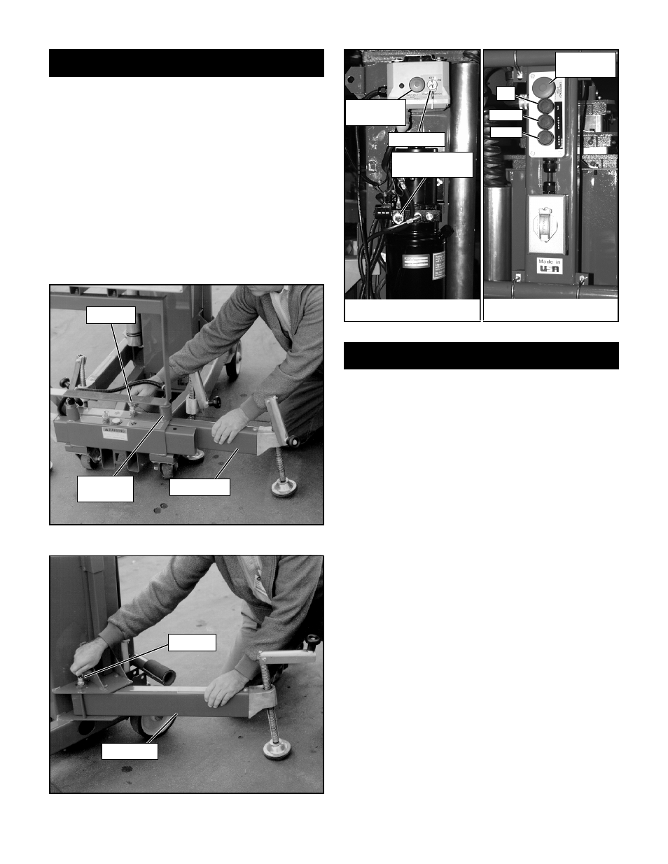
Outrigger Installation
1. Pull each front outrigger out until lockpin
engages (Figure 1A).
2. Rotate each rear outrigger out towards rear of
machine and push in place until lockpin en-
gages (Figure 1B).
3. Level the base, centering the bubble in the orbit
level, using screwjacks at the end of each
outrigger. Do not release tension on an outrig-
ger by turning screwjacks counter clockwise to
level the base.
4. All four (4) screwjack pads must be in solid
contact with a firm surface. Each interlock
switch must be engaged before the platform
will elevate.
Operation
Before operating UL Lift insure that: the operator has
been thoroughly trained on this machine, the opera-
tor has read, fully understands and follows this
Operator Manual and the Scaffold Industry
Association's MANUAL OF RESPONSIBILITIES, the
unit has been properly set up with all four (4) outrig-
gers properly installed and the base leveled, and the
machine has passed the Safety Interlock Test.
Note: Platform will not elevate unless all four
outriggers are properly positioned with screwjack
pads firmly in contact with floor and each outrig-
ger indicator lamp lit.
1. Check for external damage to the mast.
2. For AC units connect power unit plug to exten-
sion cord (12 ga.) (1.5 mm²) conductor minimum
and 50 ft. (15 m) in length maximum).
Connect extension cord to properly grounded
outlet of proper voltage and frequency.
NOTE: AC units are protected by a 15 amp circuit
breaker. If breaker trips, push button in to reset
breaker (Figure 3).
Figure 1A: Installing front outriggers
Figure 2: Controls
Platform Controls
Base Controls
Figure 1B: Installing rear outriggers
Emergency
Stop Button
Key
Switch
Emergency
Lowering Valve
Emergency
Stop Button
Up
Power
Down
Lockpin
Interlock
Switch
Outrigger
Lockpin
Outrigger