Snorkel SB126J User Manual
Page 36
Chapter 7 – Prestart Inspection
30
SB126J – 0192278
Use the following procedure to test and inspect the
EMS.
1. Turn on the ignition and start the engine.
2. From the lower controls, fully extend the boom hori-
zontally. Ensure that no more than 5 to 8 cm (2-3
′′)
of black and yellow striped tape is showing at the
end of the hose carrier. (Refer to Figure 7.15) If more
or less tape is showing, remove the machine from
service and contact an UpRight authorized service
provider.
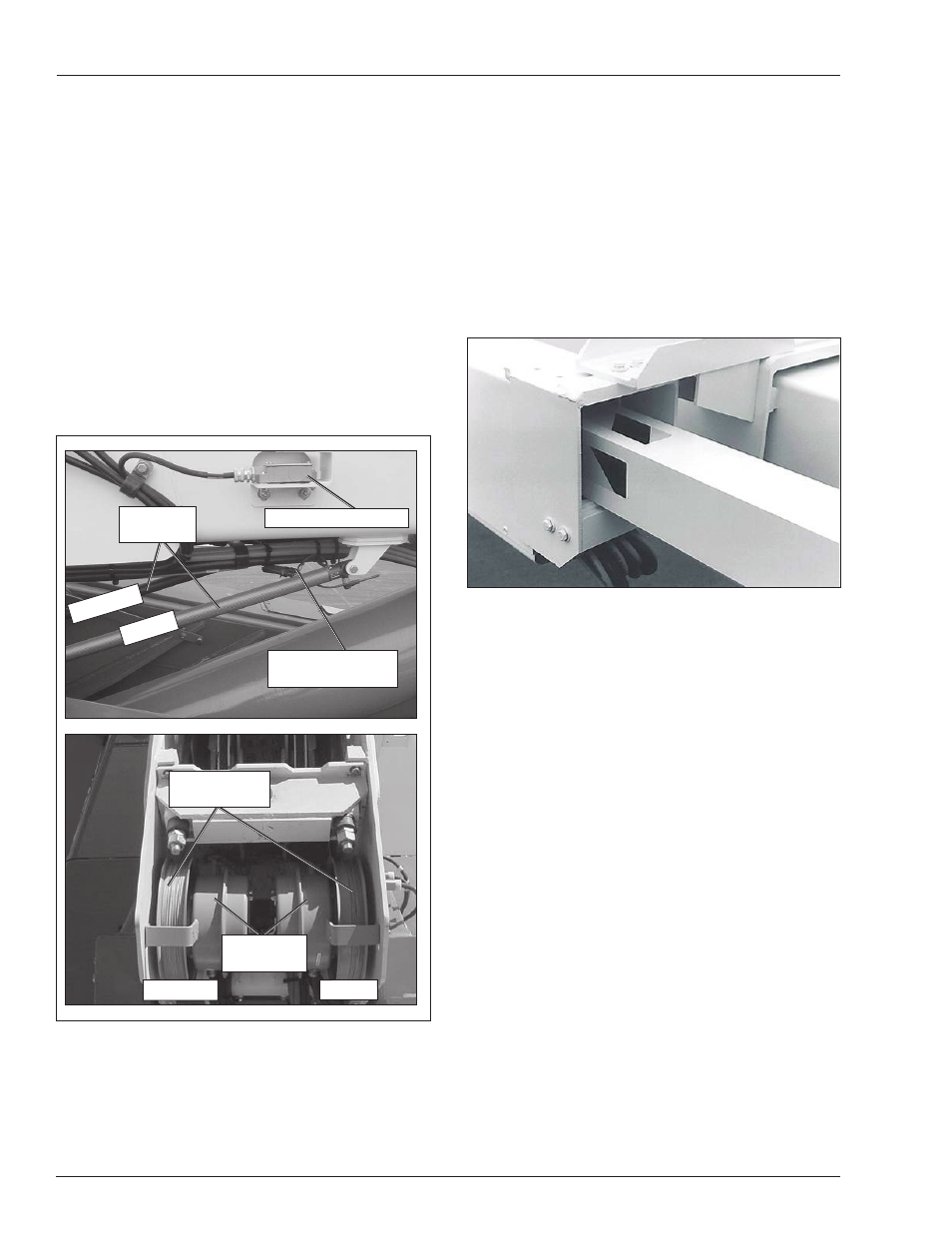
Figure 7.15 – Hose Carrier and Main Boom
3. Fully raise the boom.
4. Check the lower controls for a fl ashing green light
and check the EMS display for any error messages.
Fully lower and retract the boom. In the event of a
fl ashing green light or EMS error messages, remove
the machine from service and contact an UpRight
authorized service provider.
5. From the upper controls attempt to raise and ex-
tend the boom without depressing the foot switch.
The boom should not move and the EMS will error
out in 10 to 15 seconds. If the boom moves, or the
EMS does not error out, remove the machine from
service and contact an UpRight authorized service
provider.
6. From the lower controls, extend the boom approxi-
mately 2 m (6
′) and raise the boom to approximately
30 degrees.
7. Open the manual bleed down valve. The EMS will
error out for primary and backup length and angle
sensors. If the EMS does not error out, remove
the machine from service and contact an UpRight
authorized service provider.
Emergency Stop
Push the emergency stop button in to turn off the engine.
The lower control functions should not operate with the
emergency stop in this position.
Emergency Power
Place the battery disconnect switch, the emergency stop
button, and the master switch in the on position.
Hold the engine/emergency power switch down and the
ground operation switch upward to operate the aerial
platform from the lower controls using the emergency
power system.
Envelope Management System
Inspect and test the EMS sensors for wear, physical
damage and proper operation (refer to Figure 7.14).
Figure 7.14 – EMS Sensors
EMS Length
Sensors
Length Sensor
Cables
Primary
Secondary
EMS Angle Sensor
Connector
EMS Angle
Sensors
Primary
Secondary
Extend Cut-out Switch