Snorkel AB85RJ User Manual
Page 53
Chapter 8 – Operation
AB85RJ – 0421533
49
Calculate the percent grade:
• before attempting to climb an unknown grade
• if it is believed that there is a malfunction to determine
if the slope is within the actual grade capability of the
aerial platform.
Calculating Percent Grade
The percent grade equals the height (rise) of the slope di-
vided by the length (run) times 100. Refer to Figure 8.7.
Figure 8.7 – Percent Grade Formula
The grade can be measured with an inclinometer or by
using a tape measure, a level, and a straight 2x4. If us-
ing an inclinometer, refer to the conversion diagram if
necessary.
To measure the grade without an inclinometer, use the
following procedure.
1. With the 2x4 laying parallel with the slope, lay the
level lengthwise on the 2 x 4.
2. Holding the downhill end, raise the 2x4 until the level
indicates the board is level (refer to Figure 8.8).
Figure 8.8 – Percent Grade Calculation
3. Use the tape measure to measure the distance
(height) from the end of the 2x4 to the ground. Record
the height distance.
4. Measure the length of the 2x4 and record this mea-
surement.
5. Use the formula in Figure 9.2 to calculate the percent
of the grade.
Machine Gradeability
The gradeability specification for the aerial platform are
listed below.
Gradeability – theoretical..........................................45%
Theoretically, when all contributing factors are optimal,
the machine can be driven on a slope of 45%. A slope
with a percent grade of 45% is a slope with an angle of
24 degrees.
Gradeability – actual.................................................30%
An actual gradeability of 30%, indicates that in most nor-
mal working conditions the machine can be driven on a
slope with an angle of 16.5 degrees.
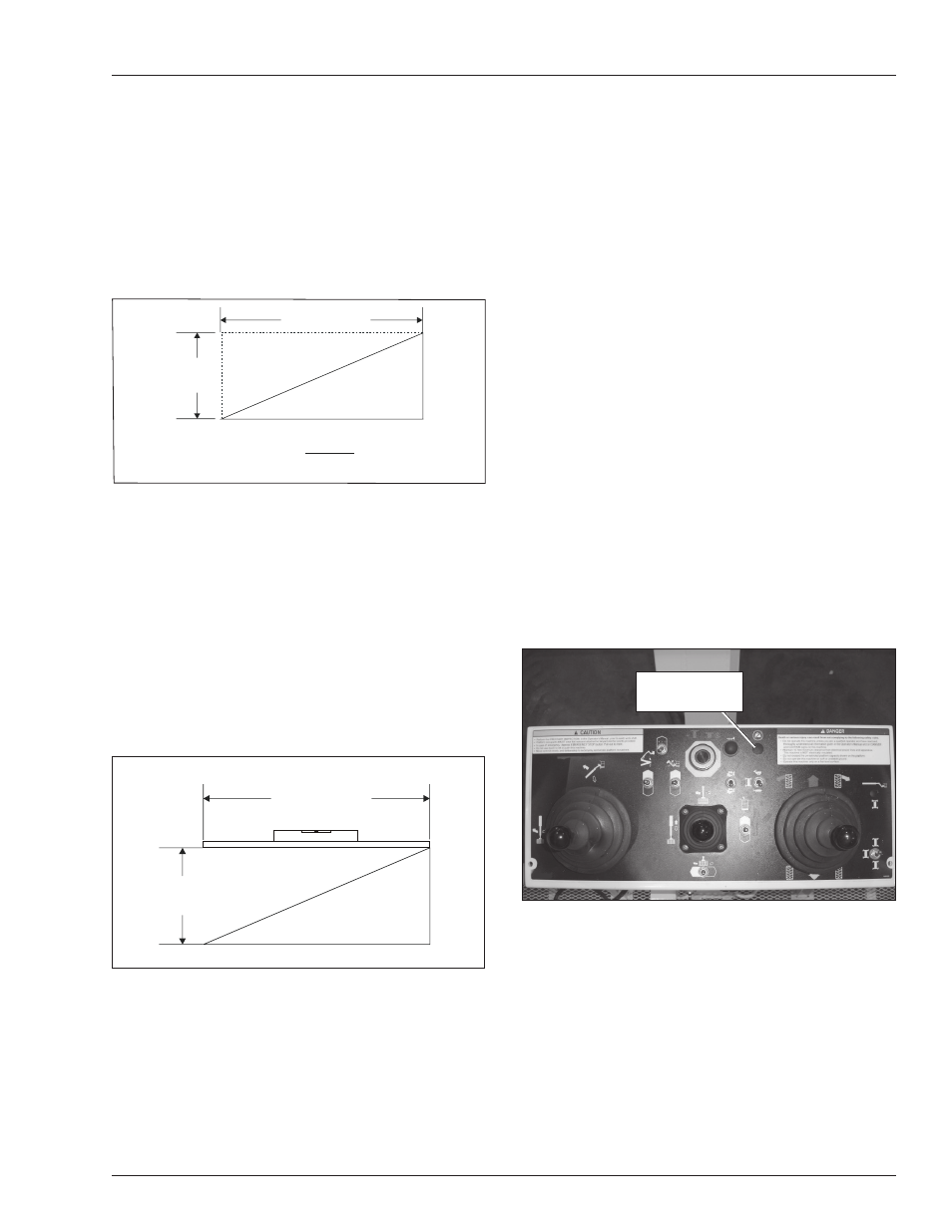
Platform Overload Sensing System
All functions are stopped from the upper and lower
controls, when the platform overload limit is exceeded.
The horn will sound intermittently and the red overload
light (refer to Figure 8.9) will blink until the excess load
is removed from the platform. At that time, the machine
functions are again operational.
Note
If the platform overload sensing system is tripped while
operating the machine, the emergency power system
may still be used for emergency machine operation from
either the lower or upper controls.
Figure 8.9 – Upper Control Panel
If the platform becomes significantly overloaded, or if an
upward force on the platform exceeds approximately
445 N (100 lb), the system will enter into error mode,
stopping all functions from the upper and lower controls.
The horn will then sound constantly and the overload light
will stay illuminated at the upper and lower controls (refer
to Figures 8.9 and 8.10).
Length
Height
Length
Height
% of Grade =
x 100
Length
Height
Ground Slope
Platform
Overload Light