Class1 120319 - Twister Electronic Throttle - ANALOG - 119971 User Manual
Page 2
ANALOG OUTPUT VOLTAGE CONFIGURATION
Engine manufacturers have different requirements for the analog
voltage input into their Engine Control Modules. Some
manufactures may require and idle voltage of 0.7 VDC and a
maximum voltage of 4.0 VDC and others may require an idle voltage
of 1.0 VDC and a maximum voltage of 3.7 VDC.
The Twister allows configuration of its minimum and maximum
analog output voltage for meeting the analog voltage requirement of
Engine Control Module. The Twister’s default analog output voltage
range is 0.25 VDC to 4.2 VDC.
Idle voltage configuration:
Enter the password -
Release the IDLE button.
Make certain the interlock input (pin 3) is active, the engine is
running, and the ECM’s remote throttle enable is active.
Rotate the Twister’s knob in the INCREASE RPM direction
(clockwise is default) until the engine’s RPM increases.
Rotate the Twister’s knob in the DECREASE RPM direction
(counter-clockwise is default) until the engine’s RPM has just
reached its natural idle RPM.
Press the IDLE button for one (1) second to save the idle voltage.
Maximum voltage configuration:
Enter the password -
Release the IDLE button.
Make certain the interlock input (pin 3) is active, the engine is
running, and the ECM’s remote throttle enable is active.
Rotate the Twister’s knob in the INCREASE RPM direction
(clockwise is default) until the desired maximum engine RPM is
reached.
Press the IDLE button for one (1) second to save the maximum
voltage.
The analog output voltage configurations are saved in memory and
will not be lost due to power interruption or by unplugging the
Twister’s connector.
KNOB ROTATION CONFIGURATION
The Twister allows the knob rotation direction for increase RPM to be
configured. The default is clockwise rotation yields an increase in
engine RPM. But this may be changed to counter-clockwise rotation
yields an increase in engine RPM by entering a password.
Clockwise rotation equals increase engine RPM (default):
Counter-clockwise rotation equals increase engine RPM:
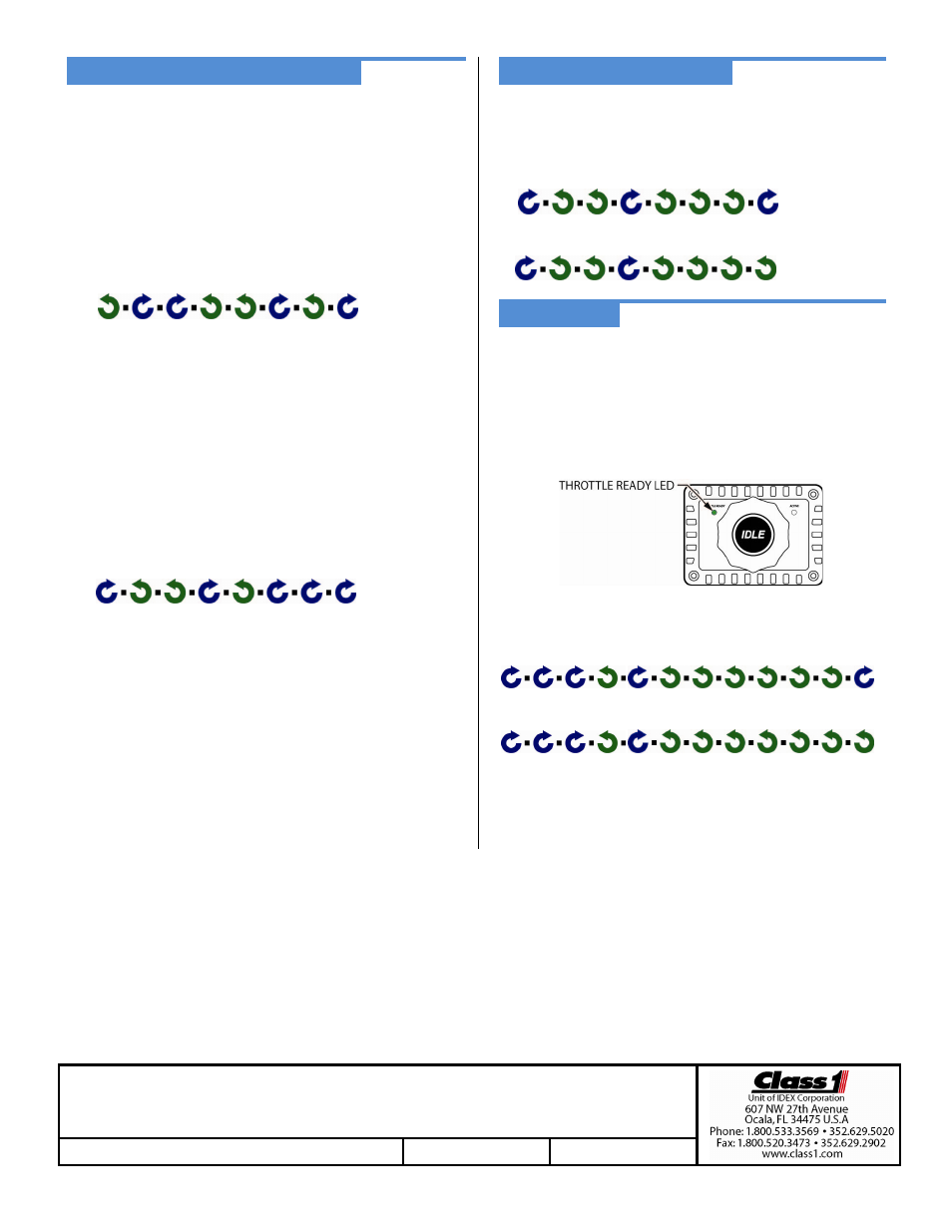
INTERLOCKING
The interlock input (pin 3) must be active before the Twister will
allow control of the engine’s RPM.
It is the OEM’s responsibility to create a safe interlocking scheme to
activate the Twister’s interlock input.
The Twister’s green THROTTLE READY LED will ON when the
interlock input is active. The Twister is now ready for operator
initiated control.
The Twister
allows configuration of the interlock input’s (pin 3)
activation polarity (positive voltage or ground).
Positive polarity interlock configuration password (default):
Ground polarity interlock configuration password:
For detailed operation and troubleshooting consult the full manual (p/n 120478) available from the Class 1
Twister (analog) OEM Quick Manual P/N 120319
REV C
9-7-2010