Flow meter, Paddlewheel installation – Class1 Digital Flow Meter User Manual
Page 6
page 6 of 9 pages
Engineering
Standards
Name
Identifier
Engineering Standard Number
C1-102046-A
Digital Flowmeter Information
C:\MANUALS\DIGITAL\FMINDER\FMINDSER.PM6_071597
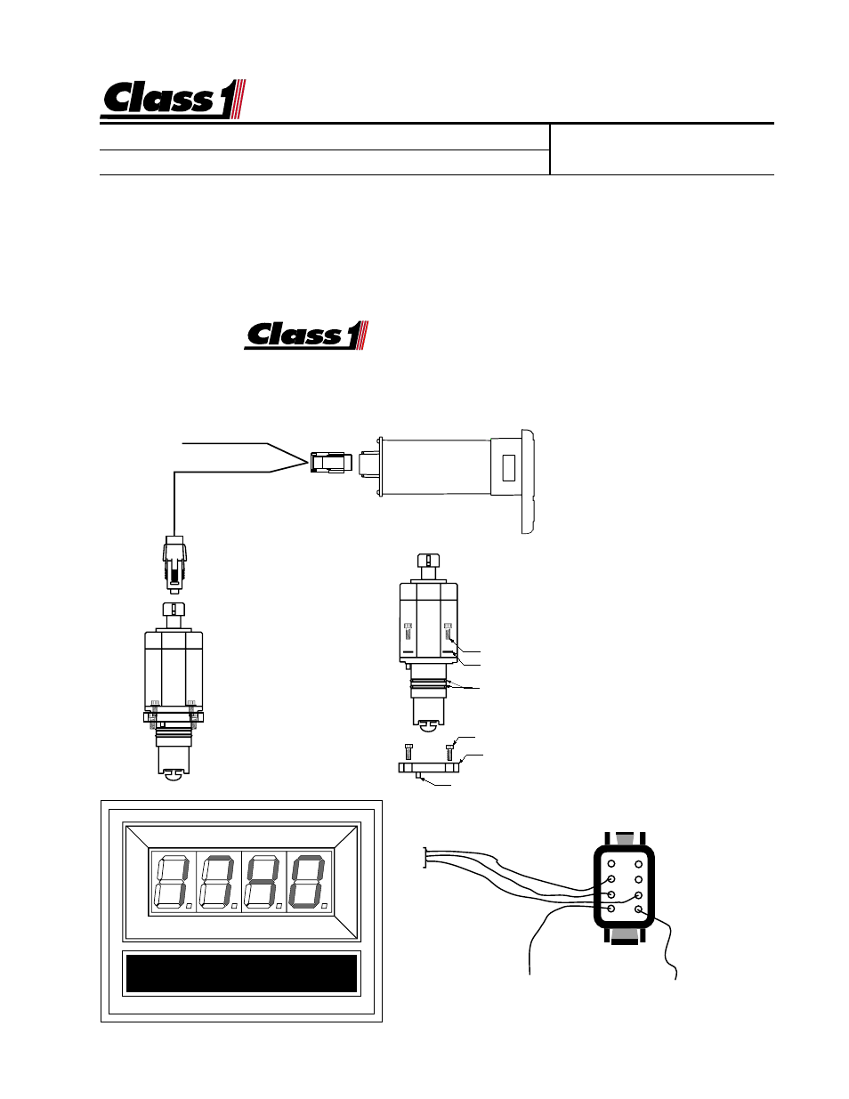
FLOW METER
Red (System Power)
Black (System Ground)
White (Signal)
DTM06-08S
1
2
3
4
8
7
6
5
Wire Insertion View
The
Class1
Class1
Class1
Class1
Class1 digital flowmeter system comes
with the digital display, a paddlewheel trans-
mitter and a connecting harness (specify
length). A method of mounting the trans-
mitter to the discharge is needed, call for
options and specify the pipe diameter.
The flow display includes a totalizer func-
tion. A momentary switch (optional) is re-
quired to operate this feature. The display
will continuously monitor flow when the unit
has power and display the latest total vol-
ume when the totalizer switch is pressed.
The total flow is cleared when power is re-
moved from the unit.
Paddlewheel Installation
O-ring
Indexing Pin
Spacer
6-32x7/16
Lockwasher
6-32x7/16internal hex
Power and Ground