Class1 Digital Aerial Warning Display User Manual
Page 5
page 5 of 6 pages
Engineering
Standards
Name
Digital Aerial Warning Display
Identifier
Installation Information
Engineering Standard Number
C1-102342-A
Calibration for dual and single transducer installations:
Calibration for Gauges with bargraph displays
The calibration mode is entered by the use of a “password”.
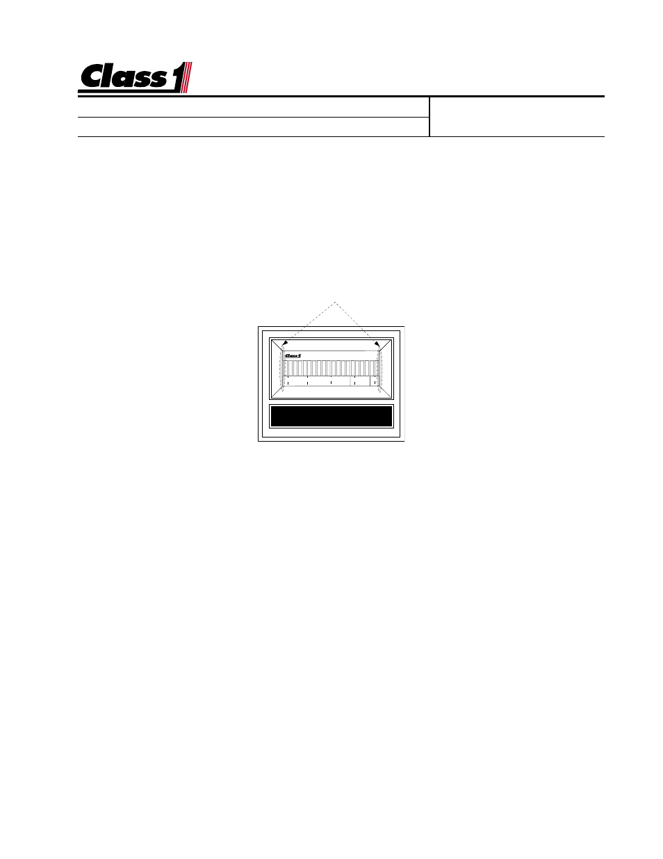
There are two magnetic switches, one located at each side of the display.
These switches are activated with the use of a magnet.
Switch activation is visually confirmed by the toggling of the closest bar on the dis-
play to the switch. If it is on it will turn off, if it is off it will turn on.
M
INIMUM
L
OAD
With the ladder retracted, just raised out of the cradle and no load
placed on the device, enter the calibration password.
L L L R R R
The left (0%) bar will flash to indicate that you are ready to calibrate for the minimum
load.
Activate the left switch followed by the right switch.
The right (100%) bar will flash to indicate that the display is ready to calculate for
maximum load.
M
AXIMUM
L
OAD
With the ladder extended and maximum load placed at the end of
the aerial device actuate the right switch and then the left switch.
Calibration is complete
NOTE:
A
ERIAL
MANUFACTURERS
MUST
ENSURE
THAT
THE
LIFT
CYLINDER
(
S
)
DO
NOT
BOTTOM
OUT
DURING
OPERATIONS
. T
HIS
WOULD
CAUSE
AN
ERRONEOUS
HYDRAULIC
PRESSURE
READING
AND
THE
WARNING
SYSTEM
WILL
NOT
OPERATE
AS
DESIGNED
.
BAR GRAPH DISPLAY
0 25 50 75 100
Location of magnetic switches