J.p.instruments, Fuel flow installation manual – J.P. Instruments EDM 760 Fuel Flow Installation Manual User Manual
Page 4
J.P.Instruments
Fuel Flow Installation Manual
Report # 760
for EDM-760 temperature indicating system with Fuel Flow Option
Appendix - A
Page Page 4 of 14 Rev NC :
Date 07/20/99
3…. Installing the Fuel Flow Transducer:
Mount the Fuel Flow Transducer using the appropriate drawing at the back of this manual.
Aircraft Configuration
Drawing #
Location
Page
1. All Fuel injected engines with vapor return lines to fuel tank
, all Continental and certain Lycoming engines.
700922
Between throttle body
and fuel flow divider.
9
2. All pump fed carbureted and Fuel injected engines without
vapor return lines.
700921
Between engine driven
pump and servo/throttle
body or carburetor
10
3. Pressure Carbureted engines with vapor return lines
700923
700920
One transducer in Carb
inlet line and one
transducer in out let line
8,
13,14
The instructions listed below must be followed when installing a Fuel Flow Transducer.
Note: If your engine is equipped with a fuel return line from the carburetor back to the fuel tank you will need to
install two flow transducers... one in the feed line from the fuel pump to the carburetor and one in the return line
from the carburetor back to the fuel tank. Also, a Fuel Flow Differential Module (Dwg. 700920) will need to be
installed.
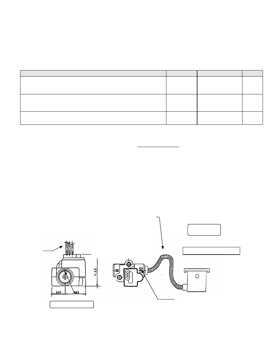
The transducer output port should be mounted lower or even with the carburetor inlet port (or fuel servo on a fuel
injected engine). If this is not possible, a loop should be put in the fuel line between the Fuel Flow Transducer
and the carburetor or fuel servo (see diagram below).
Do not remove the caps on the flow transducer until the fuel hoses are ready to be installed.
The flow of fuel through the transducer must follow the direction marked on the transducer.
END VIEW UP
If the transducer is
higher than the
carburetor or fuel servo,
put a loop in the fuel line
between the transducer
and the carburetor or
fuel servo.
Mount the
transducer
with the
wires up.
SIDE VIEW
¼ NPT
The direction of the
fuel flow through the
transducer is marked
on top
Carburetor or Servo