J.p.instruments fuel flow installation manual, Fs-450, 3installing the fuel flow transducer – J.P. Instruments Fuel Scan 450 Installation Manual User Manual
Page 3
J.P.Instruments Fuel Flow Installation Manual
Report # 400
FS-450
Page 3 of 16
Rev A : Date 02/1/2002
3
Installing the Fuel Flow Transducer:
Mount the Fuel Flow Transducer using the appropriate drawing in this manual.
The instructions listed below must be followed when installing a Fuel Flow Transducer.
Note: If your engine is equipped with a fuel return line from the carburetor back to the fuel tank two transducers are
required.
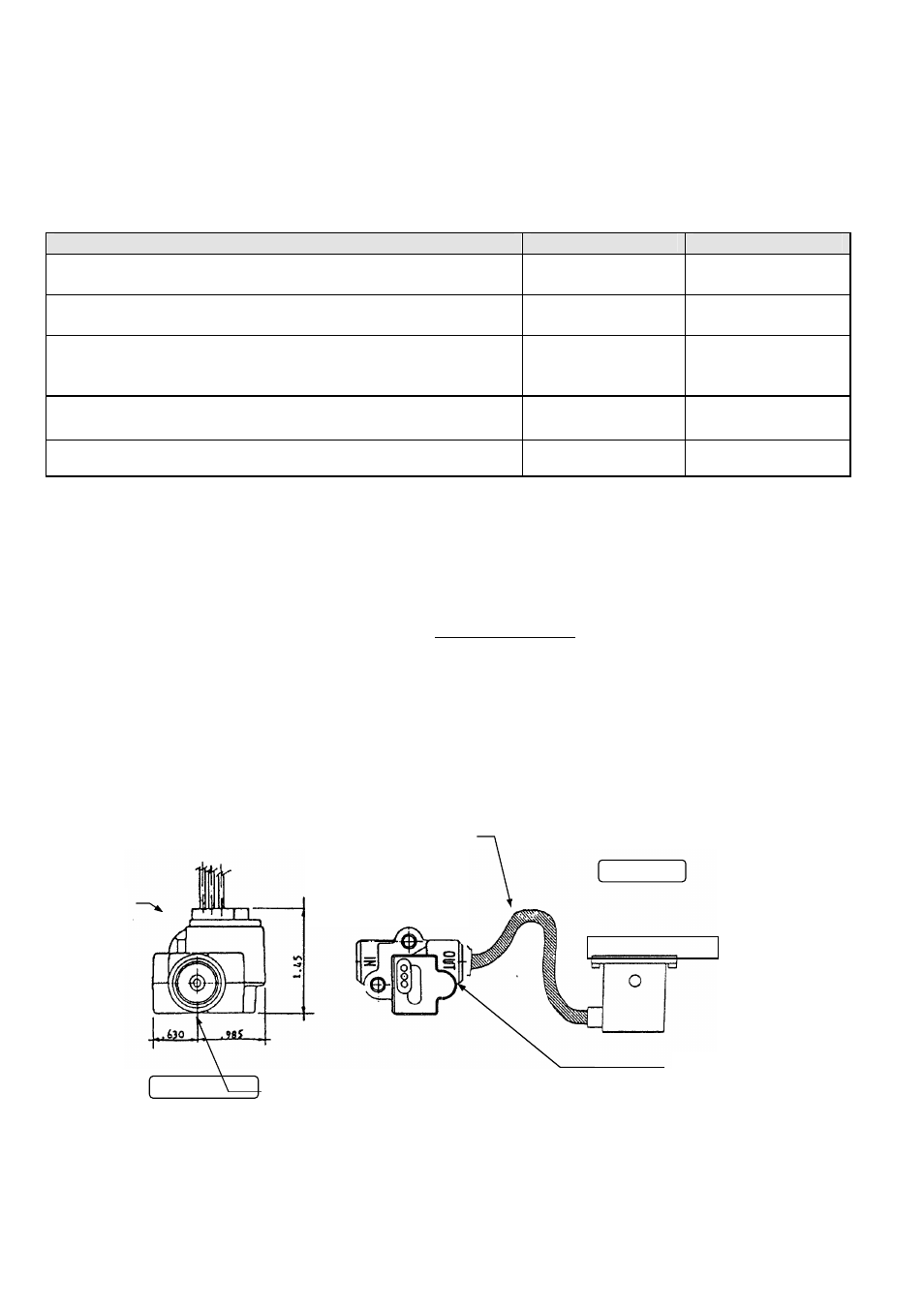
The transducer output port should be mounted lower or even with the carburetor inlet port (or fuel servo on a fuel
injected engine). If this is not possible, a loop should be put in the fuel line between the Fuel Flow Transducer and
the carburetor or fuel servo (see diagram below). It is recommended not to hard mount the transducer to the
carburetor or fuel servo.
Do not remove the caps on the flow transducer until the fuel hoses are ready to be installed.
The flow of fuel through the transducer must follow the direction marked on the transducer.
The flow transducer must be mounted so the wires exiting the transducer are pointing up.
Before connecting any hoses, thoroughly clean them and insure they are free of any loose material. High air
pressure my be used, However, do not allow high air pressure to pass through the flow transducer.
Aircraft Configuration
Drawing
Location
1.
PN 450000-G
All gravity Flow installations without fuel pump.
Must use transducer PN 700900-2
700923
Between Fuel tank and
Carburetor.
2.
PN 450000-P
All Fuel injected engines with vapor return lines
to fuel tank , all Continental and certain Lycoming engines.
700922
Between throttle body and
fuel flow divider.
3.
PN 450000-P
,-H All pump fed carbureted and Fuel injected
engines without vapor return lines. PN 450000-P range up to
60 GPH and PN 450000-H range up to 120 GPH
700921
Between engine driven pump
and servo/throttle body or
carburetor
4.
PN 450000-D
Pressure Carbureted engines with vapor return
lines. Requires Dual transducers
700924
450508
One transducer in Carb inlet
line and one transducer in
outlet line
5.
PN 450000-M- If “M” is after the PN it signifies that the display is
3” Fuel flow for twin engine aircraft single indicator.
700922
Between throttle body and
fuel flow divider.
END VIEW UP
SIDE VIEW
If the transducer is
higher than the
carburetor or fuel
servo, put a loop in the
fuel line between the
transducer and the
¼ NPT
The direction of the fuel
flow through the transducer
is marked on top
Mount the
transducer
with the
wires up.
Carburetor or Servo