Lock-n-load, Assembl y – Hornady Lock-N-Load AP User Manual
Page 10
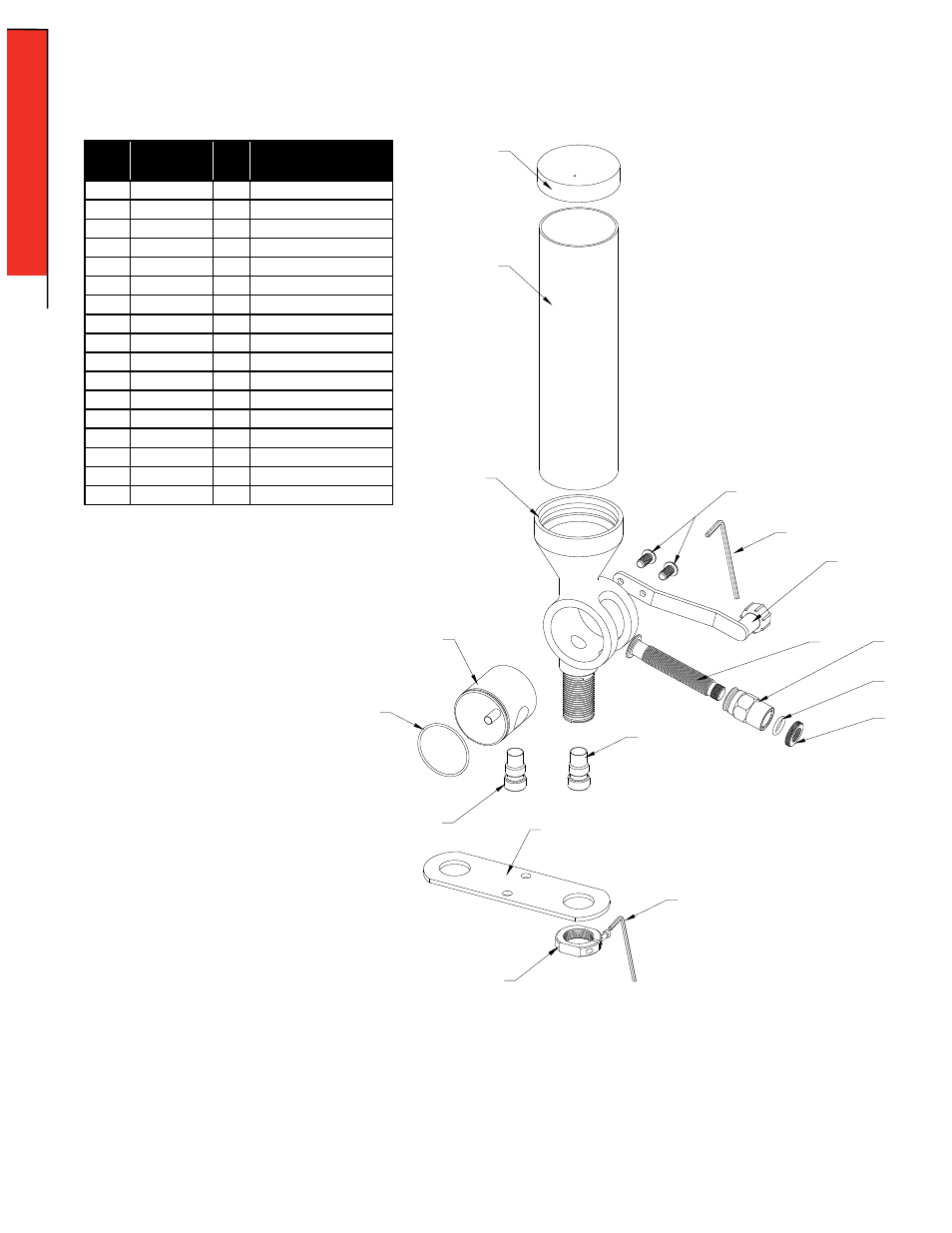
Item
No.
Production
Part Number
Qty.
Description
1
170405
1
HOPPER CAP
2
398520
1
HOPPER
3
392740
1
BODY
4
392719
2
SCREW BHSCS 10-32 X 3/8
5
392752
1
HANDLE ASSEMBLY
6
392741
1
ROTOR
7
392743
1
METERING PLUNGER
8
392742
1
SLEEVE
9
480083
1
O-RING 1/2 ID X 11/16 OD
10
392764
1
NUT LOCK METERING UNIT
11
392766
1
O-RING 1 1/2 ID X 1 5/8 OD
12
390702
1
SMALL DROP TUBE
13
390701
1
LARGE DROP TUBE
14
392760
1
MOUNTING BRACKET
15
390656
1
3/32” HEX WRENCH
16
O44000
1
LOCK RING
17
390653
1
1/8” HEX WRENCH
1
2
3
6
11
13
14
16
15
17
12
10
9
8
7
5
4
Lock-N-Load
®
Powder Measure
PARTS LIST
EXPLODED VIEW
Precautions for the
Powder Measure:
• Always change the metering units with
the handle and the metering unit in the
horizontal position, and after you have
dropped the charge. If you allow the
Handle to fall while changing units, you
will drain the Hopper.
• Be sure that you have the proper
Lock-N-Load
®
device locked in place,
before operating.
• Always verify your charges with a scale
before loading.
• Any moisture in the unit will cause
powder to stick, and charge weights will
vary dramatically.
ASSEMBL
Y
- 10 -
ASSEMBLY: POWDER MEASURE