Step 7: non-tension end step 5: electric operator, Step 6: tension end, Step 7: non-tension end – Mueller Roll-Up Door C250 User Manual
Page 7
WWW.MUELLERINC.COM
7
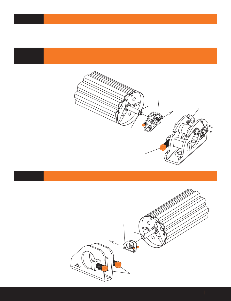
Spring Roll Pin
Dual Tensioner
Tensioning Hub
Set Screw
Wall
Axle
A
Using dual tensioner assembly’s
spring roll pin located in knurled
wheel, rotate upward in the
direction that clears the axle.
B
Slide dual tensioner assembly
vover axle and tensioning hub,
with arrow pointing toward wall.
Release spring roll pin.
Wall
Axle
Axle Support
Set Screws
STEP 7: NON-TENSION END
STEP 5: ELECTRIC OPERATOR
(OPTIONAL)
A
Install as per instruction provided in electric operator kit.
NOTE:
Use the DUAL TENSIONER and not the U-BOLT that is in the Operator Kit.
STEP 6: TENSION END
RIGHT SIDE OF DOOR
(LOOKING FROM THE INSIDE OUT)
IS RECOMMENDED
STEP 7: NON-TENSION END
A
Slide axle support over axle,
with arrow pointing toward wall.