Option a, Step 4: chain hoist drive – Mueller Roll-Up Door C250 User Manual
Page 6
6
877-2-MUELLER
Axle Support
Wall
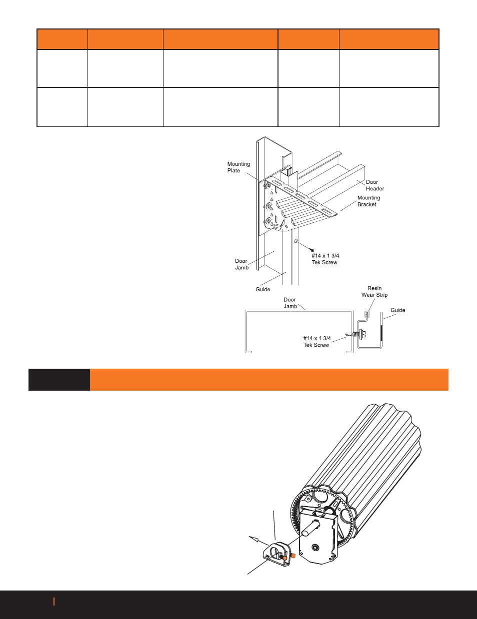
STEP 4: CHAIN HOIST DRIVE
(OPTIONAL) (N/A FOR L250 MODEL)
Option A
A
Position chain hoist assembly on door axle so that the
chain hoist gear engages the ring gear. NOTE: Do not
tighten set screws until tension has been added in Step 16.
B
The opening edge of guides should be
inset a very small amount (about 1/8
inch), from the door jamb opening on
each side to minimize the potential
of hitting the guides when enter-
ing through the door opening. Both
guides must be plumb. Note: If jambs
are installed correctly the outside to
outside measurement of guides should
be approximately 1 inch wider than
the curtain width.
C
Once both guides have been correctly
positioned, attach them to the jambs
using the appropriate fastener at each
hole location.
ITEM
JAMB
FASTENERS
DRILL SIZE
PROVIDED FASTENERS
Steel
3/8” - 1” Hex Bolt & Nut
7 1/16”
Provided
BRACKETS Concrete/Filled Block
3/8” - 3/4” Powers Wedge-Bolt
Powers 01316
Not Provided
Wood
3/8” - 7x3” Lag Screw
Optional
Not Provided
Steel
1/4” - 14x1 - 3/4” TEK Screw
None
Provided
GUIDES
Concrete/Filled Block
1/4” x 1 3/4” Powers Wedge-Bolt
Powers 01314
Not Provided
Wood
1/4” - 10x1” Lag Screw
Optional
Not Provided