Service instructions, General, Safety gas control valve & burner orifice – L.B. White I-3 Infraconic User Manual
Page 16: Thermostatic head
Service Instructions
1.
Close the fuel supply valve to the heater before
servicing unless it is necessary to have it open for
your service procedure.
2. For reassembly, reverse the respective ser vice
procedure. Ensure gas connections are tightened
securely.
3. After servicing, start the heater to ensure proper
operation and check for gas leaks.
4. Replace the burner orifice if it becomes plugged with
dirt. Do not use files, drills, broaches, etc. to clean the
orifice hole. Doing so will enlarge the hole, causing
combustion or ignition problems.
WARNING
Burn Hazard
■
Heater surfaces are extrememly hot for a period of
time after the heater has been shut down.
■
Allow the heater to cool before performing service,
maintenance, or cleaning.
■
Failure to follow this warning will result in burns
causing injury.
GENERAL
WARNING
Fire and Explosion Hazard
■
Do not disassemble or attempt to repair any heater
components or gas train components.
■
All component parts must be replaced if defects are
found.
■
Failure to follow this warning will result in gas leaks
leading to fire or explosions, causing property
damage, injury, or death.
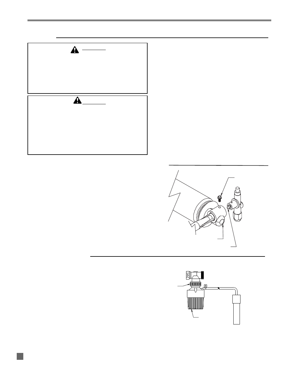
SAFETY GAS CONTROL VALVE & BURNER ORIFICE
1. Remove gas hose and disconnect thermocouple at
safety control valve.
2. Remove air intake retaining screw.
3. Pull gas control assembly from heater.
4. To remove orifice, use a 1/4 in. nut driver. Replace
orifice if plugged with dust.
FIG. 16
SCREW
AIR INTAKE
BURNER ORIFICE
ATTACHMENT
KNOB
THERMOSTATIC
HEAD
THERMOSTATIC HEAD
The head assembly on the zone panel includes the
adjustable thermostatic head, capillary and sensor. The
Part # for the thermostatic head is 23662, with 26 ft.
capillary.
The symptom of component failure would be the heater
staying at full heat output and not responding to lower
temperature setting of thermostatic head.
1. L o o s e n t h e a t t a c h m e n t k n o b l o c a te d a t t h e
thermostatic head and valve body, and discard head.
See Fig. 17.
2. Securely tighten the knob of the replacement head to
the valve body, otherwise temperature sensing will be
affected.
FIG. 17
15