Heater control and operation – L.B. White I-3 Infraconic User Manual
Page 12
Proper temperature management is needed when using the I-3
radiant heater. The creep area, which is the comfort zone for
piglets, is managed independently from the room temperature.
The room’s temperature will be lower than the temperature
needed for the creep area. Lower room temperatures create two
benefits:
-- Less fuel/energy consumption
-- Increased sow feed intake which creates higher
weaned weights.
Managing the heat in this manner provides proper growing
environment for piglets, allowing them to keep warm without
heating the sow.
Temperature Management
I-3 modulating heaters heaters are normally operated and
controlled by the use of a non- electric zone control panel.
Contact the L.B.White Co.if you are considering connecting I-3
modulating heaters to a building controller.
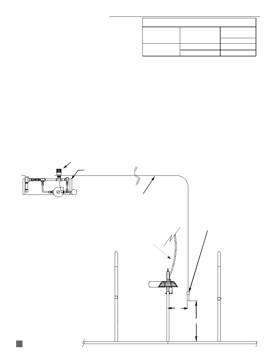
Zone Control Panel (See Fig.12)
The zone control panel is a non-electric, modulating design for
stand alone heater operation, and controls the following quantity
of heaters depending on fuel type.
The zone panel is a “heat- to- demand” operation system. It will
operate all I-3 heaters between 10% to 100% to satisfy the
temperature requirements established by the zone panel’s
thermostatic head.
The zone control panel must be mounted to a flat, stable wall
inside the building. Use lag screws provided. Ensure that the
thermostatic control module is not exposed to outside air
temperatures. Exposure of the thermostatic control module to
outside air temperatures may cause the heater to provide
unwanted heat.
Refer to Fig.12 for location of zone panel’s sensor. The sensor
must be located within a middle crate of a row of crates,
representing the average condition of the room. Do not locate the
sensor in a crate at the end of a row, or where could be
influenced by things such as cooler inlet ventilation air, exhaust
fans, opening of doors, etc.
CAPILLARY
DIVIDER
PANEL
18 IN.
CRATE
CRATE
SENSOR 8 IN. FROM
SIDE OF PANEL AND 18
IN. FROM PEN DECK
GAS HOSE TO
GAS SUPPLY
8 IN.
HEATER CONTROL and OPERATION
Modulating System
Medium
Model and
Capacity
Heat Output
Fuel
Panel
Quantity
I3
L. P. Gas
83
(2,800 BTUH)
Natural Gas
48
FIG. 12
11
ZONE PANEL
THERMOSTATIC HEAD