Buhler 2425 User Manual
Page 345
SECTION 5 - SPECIFICATIONS
5-15
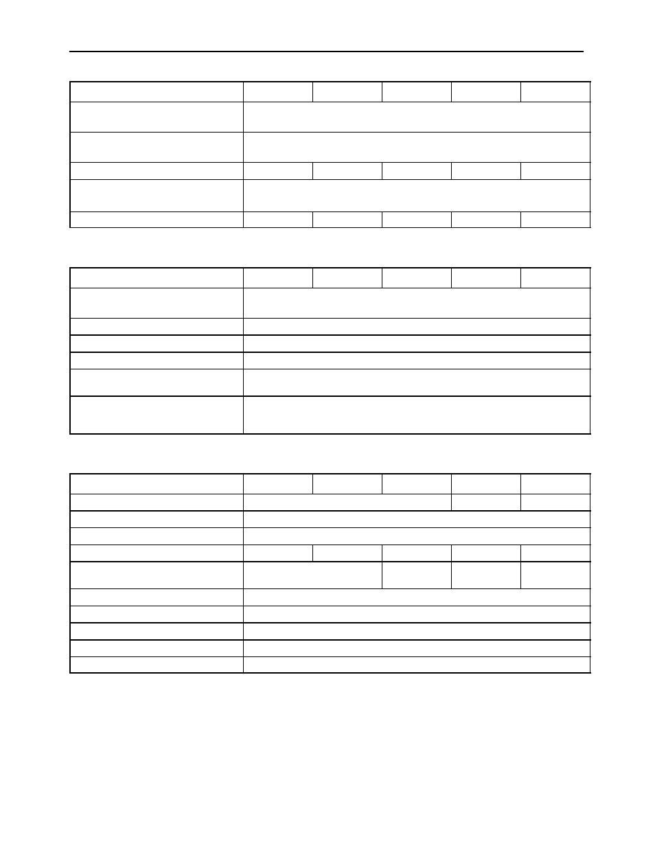
ENGINE AIR INTAKE AND EXHAUST
2290
2335
2375
2360
2425
AIR INTAKE
Precleaning
Exhaust Aspirated w/ Precleaner
Air Filter Configuration
Primary (Outer)
Secondary (Inner)
Air Flow - L/S (CFM) @ 2100 RPM
382 (810)
413 (875)
414 (878)
507 (1075)
519 (1100)
EXHAUST OUTLET
MufflerType
Perforated tube and center plug with venturi for intake. Precleaner aspiration.
Air Flow - L/S (CFM) @ 2100 RPM
798 (1690)
873 (1850)
414 (878)
1132 (2400)
1261 (2675)
FUEL SYSTEM
2290
2335
2375
2360
2425
Fuel Tanks:
Total Capacity - L (gal.)
927 (245)
Usable Capacity - L (gal.)
871 (230)
Vented
Both Tanks
Fuel Filter
Single Element
Cold Start
Measured 4.8 cc shot of fluid at each switch activation.
Thermoguard protected above 27°C (81°F)
Fuel Flow
Drawn from left tank, passes through the engine fuel system. Return fuel goes
through the fuel cooler back to the right tank. Crossover pipe between the two
tanks. Separate fill spout and drain on each tank.
COOLING SYSTEM
2290
2335
2375
2360
2425
Coolant capacity - L (gal.)
59 (15.6)
60 (15.9)
60 (15.9)
Radiator Core Size (LxW) - mm (in.)
978 x 894 (38.5 x 35.2)
Fins per Inch
9
Number of Rows
6
6
7
6
7
Fan Diameter - mm (in.) x Blade
Pitch Width - mm (in.)
813 (32)
x 89 (3.5)
838 (33)
x 89 (3.5)
813 (32)
x 89 (3.5)
838 (33)
x 89 (3.5)
Number of Blades
8
Pressure Cap Setting - kPa (PSI)
97 (14)
Thermostat Opens
82°C (180°F)
Thermostat Full Open
93°C (200°F)
Type of System
Pressurized recirculating full flow bypass with filter and corrosion inhibitor.