Cleaning and maintenance – New Buck Corporation CDVB200 User Manual
Page 29
CLEANING AND
MAINTENANCE
GLASS DOOR
Glass must be cleaned periodically. During
start-up it is normal for condensation to
form on the inside of the glass causing lint,
dust, and other airborne particles to cling
to the glass surface. During initial start-up
a slight film may form on the glass due to
paint curing. The glass should be cleaned
several times with a non-ammonia,
nonabrasive household cleaner and warm
water after the first two weeks of
operation. Thereafter, clean the glass two
or three times during each heating season,
depending on the usage and circumstances
present. Refer to Removing/Replacing
Glass Door on page 18 &19 of this manual
when removing glass door for cleaning.
WARNING: Turn off burner system
and let cool before cleaning.
CAUTION: You must keep control
areas, burners, and circulating air
passageways of burner system and
stove clean. Inspect these areas of
burner system and stove before each
use. Have burner system and stove
inspected yearly by a qualified service
person. Burner system and stove may
need more frequent cleaning due to
excessive lint from carpeting, bedding
material, pet hair, etc.
WARNING: Handle glass door panel
with care. Do not strike, slam, or
otherwise abuse glass. Do not operate
burner system with the glass door
removed, cracked, or broken.
Warning: Do not use abrasive
cleaners as this may damage glass.
Use a nonabrasive household glass
cleaner to clean glass. Do not clean
glass when hot.
WARNING: Only parts supplied by
the manufacturer should be used
when replacing broken or damaged
glass door panel (see Replacement
Parts, page 29). This glass door panel
is a complete unit. No substitute
materials may be used.
CAUTION: Wear gloves and safety
glasses while handling or removing
broken glass. Do not remove if glass is
hot. Keep children and pets away
from glass.
If glass has been broken, carefully
remove glass door (See Removing/
Replacing Glass Door, page 18 & 19).
Vacuum all glass pieces with a shop vac.
Use only the ceramic glass door
replacement intended for this burner
system (see Replacement Parts, page 29
for detail on ordering). No substitutions
may be made. See Removing/Replacing
Glass Door, page 18 & 19 for
instructions for replacing glass door.
PILOT AND BURNERS
Periodic visual check of pilot and
burner flames
•
Burner and controls should be
cleaned with compressed air to
remove dust, dirt, or lint.
•
Use a vacuum cleaner or small, soft
bristled brush to remove excess dust,
dirt, or lint.
WARNING: Do not operate burner
system with the glass door removed,
cracked, or broken.
LOGS
•
If you remove logs for cleaning, refer
to Installing Logs, page 20 to
properly replace logs.
•
Use a vacuum cleaner to remove any
carbon buildup on logs.
•
Replace logs if broken. See
Replacement Parts on page 29.
VENTING SYSTEM
Periodic examination of venting
systems by a qualified agency.
1. Check areas of venting system that
are exposed to the weather for
corrosion (rust spots or streaks and,
in extreme cases, holes). Have these
items replaced immediately by a
qualified service person.
2. Remove the vent cap and shine a
flashlight into the vent. Remove any
foreign material.
3. Check for evidence of excessive
condensation. Continuous condensa-
tion can cause corrosion of caps,
pipes, and fittings and can be caused
by having excessive lateral runs, too
many elbows, or exterior portions of
the system being exposed to cold
weather.
4. Inspect joints to verify that no pipe
section or fitting has been disturbed
and loosened. Check mechanical
supports such as wall straps for
rigidity.
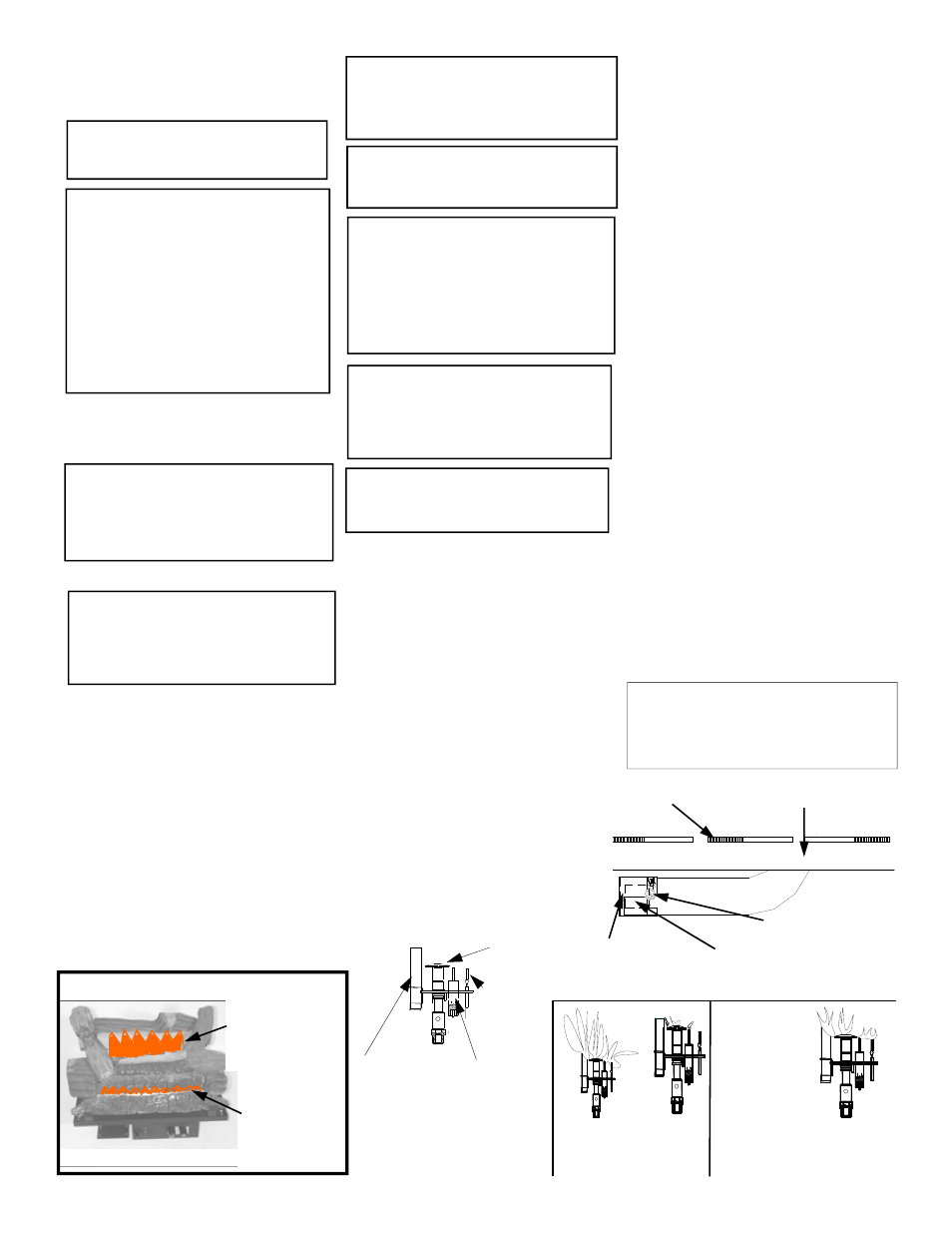
CORRECT FLAME PATTERN
PHILLIPS SCREW
AIR SHUT-
TER
AIR SHUTTER SLOTS
BURNER SLOTS
BURNER TUBE
BURNER/ AIR SHUTTER
NOTE: For direct vent design,
proper reassembly and resealing of
the vent-air intake system. (see Page
9, also Figure 20, on page 11)
Incorrect flame patterns
Correct flame pattern
PILOT
Pilot Burner
Ignitor Electrode
Thermocouple
Thermopile
CAUTION:
The appliance area must
be kept clear and free from combusti-
ble materials, gasoline and other flam-
mable vapors and liquids.
NOTE: The flow of combustion and
ventilation air must not be obstructed.
Rear Flame Should
Be Approximately 2”
to 3” Above the Rear
Log, With Yellow
Tips.
The Front Flame
Should Be Ap-
proximately 1” to 1
1/2” Up From The
Front Burner Tube,
And Be Blue In
Color.
Flame should
engulf the tip end
of the Thermo-
pile and the Ther-
mocouple, and
should be con-
stant. The flame
should be
Blue in color.
And 3/4” to 1” in height.
25