Bryant 581A User Manual
Page 23
APPLICATION DATA
1. Ductwork — Ductwork should be attached to the curb on all
units. Interior installation may proceed before unit is set in
place on roof. If ductwork will be attached to the unit, do not
drill in condensate drain pan area — leaks may result. See
figures on page 24 for information on field-installed concen-
tric ductwork when applicable.
2. Thru-The-Curb Service Connections — Roof curb connec-
tions allow field power wires, control wires, and gas supply
to enter through the roof curb opening.
3. Thermostat — Use of 2-stage cooling thermostat is
required.
4. Heating-to-Cooling Changeover — All units are automatic
changeover from heating to cooling when automatic
changeover thermostat and subbase are used.
5. Airflow — Units are draw-thru on cooling and blow-thru on
heating.
6. Maximum Airflow — To minimize the possibility of conden-
sate blow-off from evaporator, airflow through units should
not exceed 500 cfm/ton.
7. Minimum Airflow — The minimum airflow for cooling is
300 cfm/ton.
8. Minimum Ambient Cooling Operation Temperature — Units
are designed to operate at outdoor temperatures down to
35 F. To operate at lower outdoor-air temperatures, see
Trade Prices for appropriate accessories, or contact your
local representative.
9. Maximum Operating Outdoor-Air Temperature — For cool-
ing, this temperature is 120 F (180) or 125 F (155, 240).
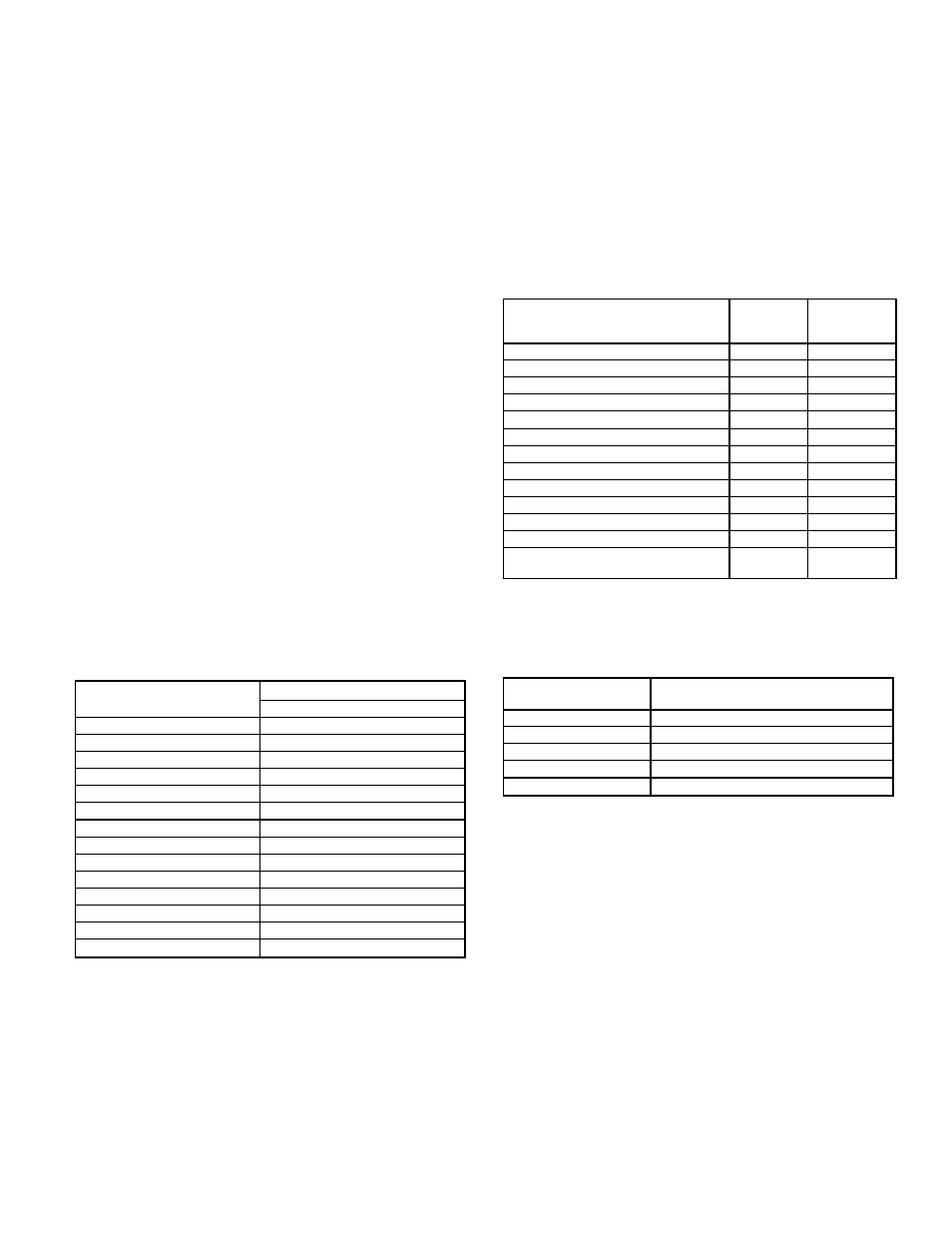
10. High Altitude — A change to the gas orifice may be required
at high altitudes. Refer to Altitude Compensation chart
below.
ALTITUDE COMPENSATION*
ELEVATION
(Ft)
NATURAL GAS
Orifice Size†
0-2,000
33
2,000
35
3,000
35
4,000
36
5,000
36
6,000
37
7,000
38
8,000
38
9,000
40
10,000
41
11,000
43
12,000
44
13,000
44
14,000
45
*As the height above sea level increases, there is less oxygen per
cubic ft of air. Therefore, heat input rate should be reduced at higher
altitudes.
†Orifices available through your distributor.
11. Minimum Temperature — Air entering the heat exchanger in
heating is 50 F continuous and 45 F intermittent.
12. Internal Unit Design — Due to the internal design (draw-
thru over the motor), air path, and specially designed mo-
tors, the full horsepower (maximum continuous bhp) listed
in the Specifications table and the notes following each Air
Delivery table can be utilized with extreme confidence.
Using the motors with the values listed in the Specifications
table
will not
result in nuisance tripping or premature motor
failure. The unit warranty will not be affected.
OPTION AND ACCESSORY LIST
ITEM
FACTORY-
INSTALLED
OPTION
FIELD-
INSTALLED
ACCESSORY
Integrated Economizer
X
X
Manual Outdoor-Air Damper
X
Two-Position Damper
X
Barometric Relief Damper
X
Roof Curbs (Horizontal and Vertical)
X
Horizontal Adapter
X
Thermostats and Subbases
X
Power Exhaust
X
Head Pressure Control Device
X
Low-Ambient Kit
X
Time Guard
ா
II Control Circuit
X
Enthalpy Control Sensor
X
Winter Start Time-Delay
Relay
X
ALTITUDE DERATING FACTOR*
ELEVATION
(Ft)
MAXIMUM HEATING VALUE
(Btu/ft
3
)
0-2,000
1,100
2,001-3,000
1,050
3,001-4,000
1,000
4,001-5,000
950
5,001-6,000
900
*Derating of the unit is not required unless the heating value of the gas
exceeds the values listed in the table above, or if the elevation exceeds
6000 ft. Derating conditions must be 4% per thousand ft above sea
level. For example, at 4000 ft, if the heating value of the gas exceeds
1000 Btu/ft
3
, the unit will require a 16% derating. For elevations above
6000 ft, the same formula applies. For example, at 7000 ft, the unit will
require a 28% derating of the maximum heating value per the National
Fuel Gas Code.
23