Bryant 581A User Manual
Page 10
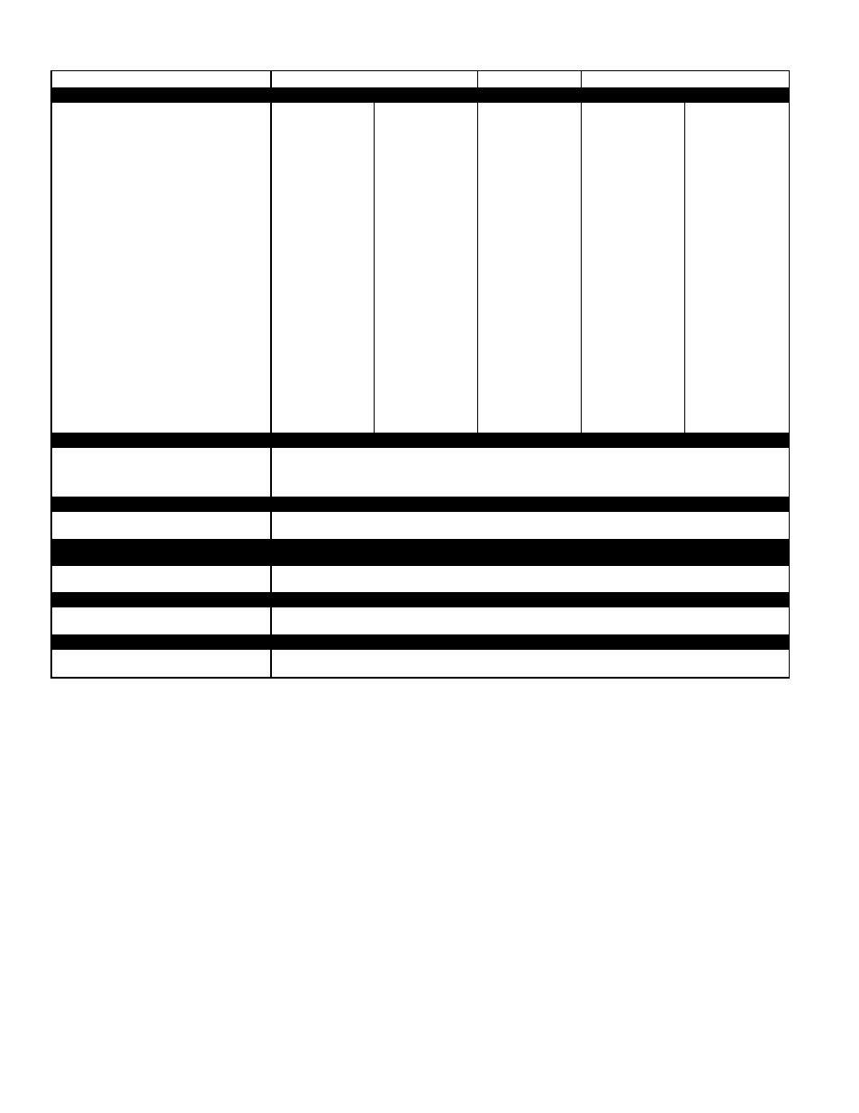
SPECIFICATIONS (cont)
UNIT SIZE
155
180
240
FURNACE SECTION
Low Heat
High Heat
High Heat
Low Heat
High Heat
Rollout Switch Cutout
Temp (F)††
190
190
190
190
190
Burner Orifice Diameter
(in. ...drill size)
Natural Gas
.113...33
.113...33
.113...33
.113...33
.113...33
Pilot Orifice Diameter
(in. ...drill size)
Natural Gas
0.55...54
.055...54,
.041...59
.055...54,
.041..59
.055...54,
.041...59
.071...50,
.071...50
Thermostat Heat Anticipator
Setting (amps)
208/230 v Stage 1
0.98
0.98
0.98
0.98
0.98
Stage 2
—
0.44
0.44
0.44
0.44
460 v Stage 1
1.20
1.20
1.20
1.20
1.20
Stage 2
—
0.60
0.60
0.60
0.60
Gas Input (Btuh) Stage 1
154,000
115,500
115,500
115,500
242,500
Stage 2
—
231,000
270,000
270,000
485,000
Efficiency (Steady
State) (%)
80
80
80
80
80
Temperature Rise Range
15-45
25-55
15-45
15-45
35-65
Manifold Pressure
(in. wg)
Natural Gas
3.5
3.5
3.5
3.5
3.5
Gas Valve Pressure Range
Psig
0.180-0.487
0.180-0.487
0.180-0.487
0.180-0.487
0.180-0.487
in. wg
5.0-13.5
5.0-13.5
5.0-13.5
5.0-13.5
5.0-13.5
Gas Valve Quantity
2
2
2
2
2
Field Gas Connection
Size (in.)
3
⁄
4
3
⁄
4
3
⁄
4
3
⁄
4
3
⁄
4
HIGH-PRESSURE SWITCH (psig)
Standard Compressor
Internal Relief
—
Cutout
426
Reset (Auto.)
320
LOW-PRESSURE SWITCH (psig)
Cutout
7
Reset (Auto.)
22
FREEZE PROTECTION
THERMOSTAT (F)
Opens
30 ± 5
Closes
45 ± 5
OUTDOOR-AIR INLET SCREENS
Cleanable
Quantity...Size (in.)
2...20 x 25 x 1
1...20 x 20 x 1
RETURN-AIR FILTERS
Throwaway
Quantity...Size (in.)
4...20 x 20 x 2
4...16 x 20 x 2
LEGEND
Al
— Aluminum
Bhp — Brake Horsepower
*Evaporator coil fin material/condenser coil fin material.
†Low-heat weight/high-heat weight.
**Weight of 14-in. roof curb.
††Rollout switch is manual reset.
NOTE: The 581A units have a low-pressure switch (standard) located
on the suction side.
10