Bryant 581A User Manual
Page 20
OPERATING SEQUENCE
COOLING, UNITS WITHOUT ECONOMIZER — When thermo-
stat calls for cooling, terminals G and Y1 are energized. The in-
door (evaporator) fan contactor (IFC) and compressor contactor
no. 1 (C1) are energized, and evaporator-fan motor, compres-
sor no. 1 (581A180,240) or unloaded compressor (581A155),
and condenser fan start. The condenser-fan motor runs continu-
ously while unit is cooling. For units with 2 stages of cooling, if
the thermostat calls for a second stage of cooling by energizing
Y2, compressor contactor no. 2 (C2) is energized and compres-
sor no. 2 starts (581A180,240) or compressor no. 1 runs fully
loaded (581A155).
HEATING, UNITS WITHOUT ECONOMIZER
NOTE: The 581A155 (High Heat), 180,240 units have 2 stages
of heat.
Set thermostat system switch at HEAT or AUTO. position and
set fan switch to AUTO. position for heating.
When first-stage thermostat calls for heat, time-delay relay for
evaporator fan begins timer sequence. Induced-draft relay
closes, and induced-draft motor starts.
Pressure switch closes and pilot valve no. 1 opens, allowing gas
to flow to the first-stage pilot. Spark ignitor ignites pilot flame.
Sensor detects flame and the main gas valve no. 1 opens. Gas
flows to main burners and first-stage burners ignite. Spark igni-
tor turns off.
When sequence is complete, time-delay relay closes and
evaporator fans start.
Second Stage — 581A155 High-Heat and 581A180,240
Units — With an additional heating call, the second-stage ther-
mostat closes. (The control relay closes during the first stage of
operation.) Pilot valve no. 2 opens, and the spark ignitor ignites
pilot. The sensor detects a flame and energizes main gas valve
coil no. 2, opening main gas valve no. 2. Gas flows to the main
burners, and the second stage burners ignite. The spark ignitor
turns off.
When the second-stage thermostat is satisfied, the second-
stage gas valve closes.
When the first-stage thermostat is satisfied, the first-stage gas
valve closes. The induced-draft motor turns off, the time relay
opens, and the timer sequence begins. When the sequence is
complete, the evaporator-fan motor turns off.
COOLING, UNITS WITH ECONOMIZER — Upon a call for
cooling, when outdoor ambient is above the enthalpy control
setting, the economizer damper moves to VENT position. The
compressor(s) and evaporator and condenser fans energize.
Upon a first call for cooling, when outdoor ambient is below the
enthalpy control setting, the evaporator fan starts and the
economizer is fully open. The compressor(s) remains off.
Upon a second-stage call for cooling, compressor no. 1 is en-
ergized and mechanical cooling is integrated with economizer
cooling. If the outdoor-air temperature drops below 50 F, a cool-
ing lockout switch prevents the compressors from running.
When supply-air temperature drops below a fixed set point, the
economizer damper modulates to maintain the temperature at
the fixed set point.
A freeze protection thermostat (FPT) is located on the evapora-
tor coil. It detects frost build-up and turns off the compressors,
allowing the coil to clear. Once frost has melted, the compres-
sors can be reenergized.
HEATING, UNITS WITH ECONOMIZER — Outdoor-air damper
stays at VENT position while evaporator fan is operating. Refer
to Heating, Units Without Economizer section above for remain-
der of operating sequence.
LEGEND FOR TYPICAL WIRING SCHEMATIC
BRK W/AT — Breaks with Amp Turns
C
— Contactor, Compressor
CLO
— Compressor Lockout
COM
— Common
CR
— Control Relay
CT
— Current Transformer
DM
— Damper Motor
FPT
— Freeze Protection Thermostat
GND
— Ground
HPS
— High-Pressure Switch
HR
— Heat Relay
HV
— High Voltage
IP
— Ignitor Pilot
ICP
— Ignitor Control Pack
IDR
— Induced Draft Relay
IFR
— Indoor (Evaporator) Fan Relay
LOR
— Lockout Relay
LPS
— Low-Pressure Switch/Loss of Charge
LS
— Limit Switch
MAT
— Mixed Air Thermostat
MGV
— Main Gas Valve
MV
— Main Valve
OAT
— Outdoor-Air Thermostat
OFC
— Outdoor (Condenser) Fan Contactor
PGV
— Pilot Gas Valve
PL
— Plug Assembly
PRI
— Primary
PV
— Pilot Valve
SN
— Sensor
TB
— Terminal Block
TDR
— Time-Delay Relay
TR
— Timer Relay
TRAN — Transformer
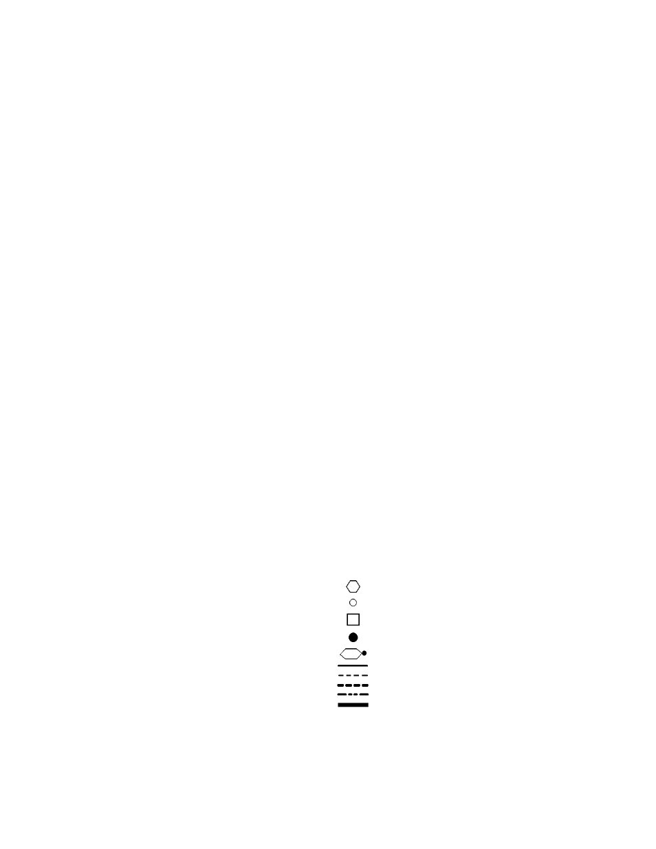
Terminal (Marked)
Terminal (Unmarked)
Terminal Block
Splice
Splice (Marked)
Factory Wiring
Field Control Wiring
Field Power Wiring
Accessory or Optional Wiring
To indicate common potential only; not to represent wiring.
20